Toshiba Satellite M35X model is known for it’s power connector problem. This issue has been covered on this blog a few times before in the following articles.
Toshiba Satellite M35X and Satellite A75 power jack and battery charge problem
Failed power jack workaround (guide for a Satellite A75 notebook similar to Satellite M35X)
Here’s another well written and documented guide submitted by Stephen Macuch. Thank you Stephen for the great pictures and very detailed instructions.
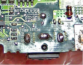
This is a view of the laptop power connector before the repair:
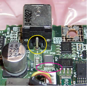
Inside the yellow circle is the main power connection from the connector to the board – note that you can see a dark circle completely around it, indicating that there is no solid metal connection.
Also note that it looks somewhat ‘burnt’ – this is indicative of sparking taking place. This connection carries 3 amps of current. The current then passes through the component labeled PF1 ( literally ‘Power Fuse 1’). It then is supposed to connect to this side of the part circled in red (‘PL1’) – but notice that flexing of the board as the connector was wiggled caused a crack you can see running horizontally under this end of this part.
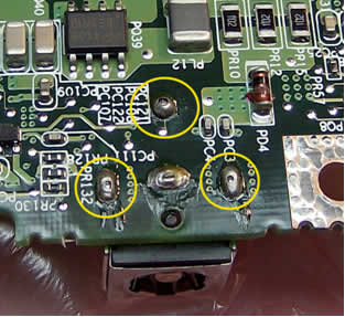
Same view, after the repair:

The green coating covering the metal leading up to the power connector was scraped off down to the bare copper of the board, in three places – the center pin, circled in yellow here, and the connector pins on both sides (see below). All were resoldered – on the top side of the board first, then touched up on the bottom (which is not where the primary electrical contact is made). The new broader, smoothly-tapered connection will be both physically stronger, and a better electrical connection.
Inside the red circle, you can see this was done for other part (PL1), as well.
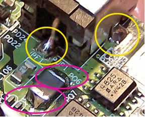
Bottom view of connector, before the repair:
Again note that inside the circled areas, you can see dark circles where there should be solid metal, indicating that the original physical connection has been broken, and the parts are only transferring power due to the fact that they are touching . In fact, the only thing even holding the connector to the board is the connection in the bottom middle (between the two lower yellow circles) and it has a crack in it, as well.
Notice, also, the dried flux residue, indicating that this bottom-side soldering was done entirely, or touched up, by hand – and not cleaned afterwards.
The actual metal that conducts the power is actually of the top side of the board, where the connector is mounted, but the fact that the solder that flowed through mounting holes has cracked indicates is was not properly soldered in the first place.
As you can see in the two views below, all solder joints between the connector and the top side copper on the board now look much better. Increasing the size and coverage of the solder joints to the metal sides of the connector will make its mounting to the board physically much stronger as well, and better able to resist any side-to-side or up-and-down forces.
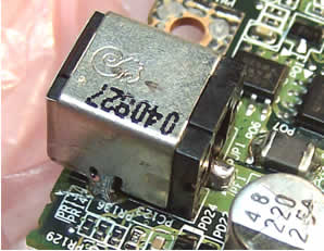
Inside the red circles, you can see that both sides of that part PL1 have been well resoldered.
This bottom view of the board after the repair shows good flow of solder through to the bottom side at the time the joints were resoldered.
Here’s another common problem with this model:
Laptop locks up, freezes up or reboots when you touch the speakers
64 Responses
patrick
hi,
are there any tutorials for acer notebooks?
thx patrick
cj2600
liam,
Witch connector you are asking about, there are four of them. 🙂
OK.
First you disconnect the wireless antennas – top two arrows. Firmly grab the connector with your fingers and lift it up until the antenna cable is disconnected from the board.
Second, you disconnect the video cable. Grab by the sides with your fingers and move towards the screen. There is no lock on this connector.
Third, disconnect the power switch board cable (blue cable). This connector has a lock on it, so be VERY careful. Carefully open the lock by moving it to the left, towards the power switch board. After the connector is unlocked, pull the cable.
Forth, unplug two more connectors.
Ki Fischer
HELP!!!!!!!!!!!!!!!!! I tried the modified dongle, sigh… it didnt work. I have a toshiba M30 Satellite. Can you please help????????
Ertan Pilevne
I have a Hp Compaq NX 9010 laptop.
Laptop’s original charger is exploding.
I’m taking a new charger.
Laptop is working only with battery.
But not working with new charger.
Charge ligth is not on.
May be laptop mainboard charge parts is failure.
Can you help me with on picture.
Which parts must be replacing?
I am testing charge parts of motherbord, but not find failure.
Please help me.
help
I HAVE THE EXACT SAME PROBLEM BUT IT IS AM115 CAN YOU HELP BECAUSE THE PART LOOKS DIFFERENT
me
hello
i am experiencing the exacrt same problem. except i have got a toshiba M115, and upon opening it up i learned the part and motherboard configuration are completely different than described above. can you help? thanks
cj2600
Here’s some help for Toshiba Satellite M115 notebook. In this model the power jack is located on a pigtail cable. You don’t have to unsolder the jack from the motherboard. When you remove the motherboard, you unplug the broken jack and replace it with a new one. No soldering job needed.
You can find a new power jack for Satellite M115 by the following part numbers: V000924240, V000926490 (for 15V power adapter).
BTW, before you replace the power jack, make sure it’s not a problem with the AC adapter. Test your adapter with a voltmeter and check if the power cuts off when you move the power cord. In this case you’ll have to replace the adapter and most likely there is nothing wrong with the power jack.
Jeff
I have tried the original Toshiba fix using some electroinc solder I had around the house, however, by the time the battery was done charging the connection was loosened up apparently from the generated heat. If anyone has a successful fix that has lasted 6 months or better a year or more would you let me know what type of solder you used? I ordered a new jack and have not installed it yet, wanting to hopefully get it right the 1st time.
Thanks
Jeff
PS if it is of any help I have the Toshiba M35X S149
cj2600
Jeff,
I’m using just regular solder, not sure exactly what type it is.
To make it work properly you have to remove the power jack, then clean contacts on the motherboard and pins on the power jack, apply fresh coat of solder on contact and pins and then solder the jack back in place.
me
hello i am having the exact same problem with a satellite m115 but the part is different when you open it up, it is under warranty but i dont want to send my hard drive away in the mail and potentially lose data…
though the symptoms are exactly the same, since the part is different, is it the same problem? i wonder because if it is the dc jack part, then why wouldnt the computer start if the battery has a charge on it? is it the power is routed via the dc jack and if the part goes bad then the whole unit wont power up? i want to make sure before i go get the part and do the repair, thanks!!
Sommay
Anyone what is the part PL1circle in RED on above image. The PL1 part on my board is burned the end close to DC jack.
sommay
Anyone know what is the part PL1circle in RED on above image. The PL1 part on my board is burned the end close to DC jack.
Jon
I have the M35X-S161 and I resoldered the power jack. Thank god that it worked.
But, I ran into another problem. My laptop can charge and sometimes will boot correctly. But often, the laptop fans will receive power, but nothing else receives power (no LCD, can’t open DVD drive, wireless led not on).
It doesn’t seem to attempt to perform POST. Please drop me an email and I can keep you updated on if it’s fixed (so you or I can post the solution)
cj2600
Jon,
It could be memory related problem, maybe the memory module is not making a good contact with the motherboard. Try reconnecting the memory module, try installing it into a different slot on the motherboard, clean memory contacts.
Also, it’s possible the memory is going bad. You can test the memory module with Memtest86+ utility.
Run this test overnight, so it passes a few times. If you’ll get memory errors, move the memory module into the second slot and test again.
If your memory fails test in both slots, most likely you have a bad module and will have to replace it.
If your memory fails test only in one slot, there could be something wrong with the memory slot itself. You’ll have to replace the motherboard or use the laptop only with one memory module installed into the working slot.
I hope this explanation is clear enough.
cj2600
Jon,
When you start a Toshiba Satellite M35X laptop without any memory modules installed you have to get a beep error, something like one short – three long – three long – one short. If you laptop will not beep when both memory modules are removed, most likely there is a problem with the motherboard. Just make sure the laptop volume is turned on, set the volume wheel somewhere in the middle.
jason
I have a toshiba satelite pro 4600, The power jack
has to be wiggled to charge the battery and then
I have to unplug the charger to use the laptop
or the screen wont come on. Is this the same power jack problem and do you have instructions
on taking this thing apart? My dad can solder the
bad connections for me. Your help would be apreciated. THANKS
rick
Great site!
any idea why my toshiba satelite pro runs so hot that the keys are very warm?
it works fine.
Nothing has ever been done to the laptop
thanks
rick
cj2600
Rick,
It’s possible that the heat sink is clogged with dust. Try cleaning the heat sink with compressed air. Just spray air inside the air intakes on the bottom and clean the heat sink. It may help.
Sirat
How to reinstall Window XP over Vista ? ( On Sony VGN100GLaptop )
The problem with this computer is that I booted windows Vista onto it, decided I did not like Vista, and then went to install XP back onto the computer. Here is where the problem comes in…Upon installation of windows XP, I realized that I had just written over Vista instead of replacing it, so then I went back to do a full system recovery, which comes factory standard on the notebook (pressing F10 on the boot screen). Long story short, the recovery did not fully complete itself for whatever reason, and I now get the black screen that says “Error Loading Operating System” whenever booting the computer up.
Thank you.
cj2600
Sirat,
Here’s what I did when I had the same problem. I downloaded Active@ Kill Disk – Hard Drive Eraser and erased the hard drive. I didn’t erase the whole drive, just went through 1-2% so the beginning of the drive is clear from Vista files. After that I was able restore XP from scratch, not just install it over Vista.
If your XP recovery files are located on a separate partition on the hard drive, I would STRONGLY suggest creating recovery discs if you can. Just in case if something goes wrong and your recovery partition is erased.
Ariel
Hello.
I hope that this topic could help me but after dissassebly the lap, i saw that PF1 seems burned, i mean there is a small solder droplet in it. Is it possible to change it? Is there anyway to circumvent this issue? thanks in advance for your time.
cj2600
Ariel,
I think you are talking about the power fuse, right? Yes, it’s possible to replace the fuse but you have to have soldering experience.
You can remove the motherboard, take it to a local electronics repair shop and ask them to replace the fuse. It shouldn’t be very expensive.
Be careful. The motherboard is static sensitive. Don’t touch components. Carry the motherboard in an ESD-protective bag.
Ariel
Thanks for your kind reply.
I think that in my small town it will be a little bit hard find someone that can do it, and i would like to do it myself.
Do you know how to get that fuse? What are the specs? If you have some time, i would like to hear any extra comments or tips.
thanks in advance.
cj2600
Ariel,
I don’t know the specs. Take a closer look at the fuse. Maybe it has value written on it.
Sid Sandback
Hi.
I have a Satellite A70 and the Power Jack needs to be soldered as described, but there is one screw that I can’t figure how it comes out to take the laptop apart. It is buried in the assembly and seems to be almost impossible to take apart. Can someone help me on the procedures to take apart the A70?
Thanks
Cornelius Johnson
Where exactly do you run the wire from the positive pin? The sleeve came up when the dc jack was pulled off? From veiwing the diagrams and the reading you said to run it from the top to the bottom.
LAURA
I HAVE A PROBLEM WITH MY TOSHIBA SATELLITE A135-S2356 IT SEEMS THAT THE FAN IT WORKS AS ANOTHER PROBLEM OF TOSHIBA YOU MENTION NO IMAGE IN LCD SOMETIMES THE LIGHT SEEMS TO WORK AND AFTER THAT IT’S DEAD, I TOOK THE BATTERY, HARD DRIVE, MEMORIES BUT THE READING DISK CAN NOT OPEN, I PUT A NORTON INSIDE TO SEE IF IT WAS A VIRUS BUT IT GOT STUCK SO I CAN NOT TAKE THE DISK OUT ANY MORE i’M AFRAID TO OPEN THE WHOLE LAPTOP, SO WHAT YOU RECOMEND? IT WILL COST ME A LOT TO REPAIRT IT?
THANK YOU.
LAURA.
mohammed ali
my toshiba laptop not working .same dead.not com light and like this one technician tell me mother bord problem please give me a best respond.
cj2600
Mohammed,
I assume you are asking about a Satellite M35X laptop.
1. You’ll have to test the power adapter and make sure the voltage output is correct.
2. Wiggle the power plug inside the jack. If the power LED flickers when you wiggling the power jack, most likely the power jack has to be resoldered or replaced.
3. If the power jack is not loose and the power LED will not light up or flicker at all, there could be a problem with the motherboard.
seanjim78
just to say thx, first time i ever took a computer apart,
apart from surfing the web thats all i know about computers.
info here was what i needed to confirm what went wrong thx again
Ivan
Hello there.My laptop is toshiba m35x like this gray one.I have problem with recharging the batery.Windows tell that the batery is into computer but the computer doesnt charge it.When i restart the computer the LED for battery lights for about 4-5 sec and then stops.I flashed the bios but didnt work.Any suggestions ?
Virginie Ansanay
Thanks a lot for your very helpful guide (good pictures !). It helped me a lot to disassemble my Toshiba MX30 and to fix the problem of battery charging and power connectivity.
Brian
I am wondering what the part number pf1 is so I can buy a new one for this laptop m35x-s161. I got it used and it clearly has a problem where it blew out or something also the power jack looks like someone tried to fix it but did a horrible job. If this doesn’t fix the boot up, which wouldn’t surprise me, then what is the next possible cause? I read that the speakers need to have a good ground where is that exactly that is being mentioned?
cj2600
Brian,
PF – power fuse? I don’t know the value of the fuse, but I think it could printed on the fuse.
I mentioned about top cover grounding problem in this post.
Alex
I am looking for a replacement for PL1, but I need to know what PL1 is. Does anyone know any specs about this part or where I can locate such information? I’ve already tried the National Parts Depot and Toshiba and they were unable to help me. Please reply soon.
ikov
I got M30X laptop, and there is a problem with power. When I try to turn it on (battery or cable) CPU fan work for 3s, and nothing happen – only power button and leds showsthet laptop is working. When i turn it on pressing the power connector (even without power cord connected) it starts normally… until I relese pushing this connector. It works the same way without battery – only with power cable – when I pulling the plug up.
My friend desoldered and check power connector – it seems to be OK, then solder it wery precisely and still works the same. Do you know what can be wrong with this connection/MB?
seanjim78
back again, my fixed satHELLite, has same problem again dc jack came away from the board thingy, what about wiring outside of laptop. adviseable or no
cj2600
seanjim78,
Apparently, you didn’t solder it properly the first time. Make sure all contacts on motherboard and jack are clean and coated with fresh solder. Solder it back in.
If you do a good job, the repair should last.
garry oleary
Well after taking my toshiba to the authorized toshiba warrenty repair people, inacomp on 12mile in southfield michigan and leaving a $45.00 diagnostic fee whether they fix it or not…lol really no kidding. they told me that a new part was $450.00 including labor and that it would be more cost effective to just buy a new computer. Thanks I left the forty-five dollars and ran out of the place, feeling glad that they didn’t robbed me of my wallet and cards too…lol. after looking at this blog and the great photos I decided to tackle the problem myself. now mind you I’ve never opened a laptop before and I’ve never seen a circut board either, but I managed to get the thing apart and open enought to see the circuit board and power connector, and as I was chewing my wrigley sperimnent gum, I decided to slip the doubled over wrapper in between the circuit board and the connector. And to my amazement the power light lit up and so did the charging battery light too. I’m not recommending this as a solution, but it worked for me….thank GOD…I can’t afford another computer or $450.00 for repairs….lol
calilily
Hi
I recently purchased a secondhand Toshiba equium L20-264 that wouldn’t charge the battery, even a new one. The orange charge light would stay constant for about 10 mins then blink non stop when I plug in the ac adaptor. Power meter says unknown remaing 0% charging. After taking the laptop apart I notice that the PF1 component looked damaged, like the description ‘it looks like a droplet’. I came across a forum when someone said that they managed to repair the PF1 (power fuse 1) by resoldering the connection and solved his problems. Another comment was to replace it with some sort of resister to protect power surge. I was wondering if anybody has tried this? and if using a resister, what amperage should it be?
yozhic
thank you! I fixed the yellow circle but the problem continued! after seeing your website, I fixed the red circle too and everything is great! God bless you!
Thomas Dorsch
yozhic Says:
January 8th, 2010 at 6:31 pm
thank you! I fixed the yellow circle but the problem continued! after seeing your website, I fixed the red circle too and everything is great! God bless you!
Yozhic, bless Danic’s paypal account with a few samolians!
I couldn’t correct this problem with out removeing the power jack entirely. There is not a proper solder to the top of the PC board. After cleaning the board up and providing two connections(top & bottom of the PC board) soldered positively, I inserted a wire to both 19V+ and neg connections and relocated the power plug externally.
It may not look OEM brand new… but it’ll last way longer than those. (the constant plugging/unplugging takes a toll on thr PC board connections)
oh BTW: it cost nothing to fix (if u have the tools)
debojit
hi experts,
im from india and i got a toshiba m35x gift from my cousin from USA. ok the problem is the adapter pin is loose i have to keep touching or spin it around to get the power so that the laptop starts. my battery do not charge at all so i thought maybe the problem is with the battery and i ordered for a new one but today after getting the new battery and also a new adapter the new battery did not charge at all. when the laotop is off the orange light of charging indicator does show but it never charged the battery at all amd whem i turm the laptop on the orange light dissapears, and the new adapter is also having same issue its kinda loose kile the old one, i thought after buying a new one the problem may get solved but never did. now the guy from the shop who brought me the new adapter and new battery is saying he have to replace the connector of my m35x and the problem will get solved and battery will charge. do you think i should get him to replace the connector? and one last question by any means is my old battery actually not gone bad but it stopped charging bcoz of the adapter pin issue?
thanks in advanse please someone guide me asap.
Robert G
Can anyone tell me how many of the screws on back of toshiba mx35 have to be taken out to get to the motherboard? I have taken out all the screws on the perimeter (about 10) and the back is still tightly attached. I just do not want to take out any that if not necessary.
riyas
i hav one laptop hp dv6.taht screen has brokn.how to replace?replace simple or not.which tools need for this?
riyas
my laptop turnd on but no disply…i did check ram and hd….i thing it has grapicscard problem….how to fix this problem…pls help me
cj2600
riyas,
In most laptops the graphics card is integrated into the motherboard. If the graphics card fails, the whole motherboard has to be replaced.
What is your model number. In some models the graphics card failure is a known issue. For example, HP Pavilion dv2000/dv6000/dv9000.
Gord
Just looked at your pics on Toshiba M35X – very helpful, though mine is a Toshiba Satelite E100 with a similar physical power connection problem – would this be the same idea to repair?
Thanks.
cj2600
Gord,
In a Satellite E100/E105 the power connector is not soldered to the motherboard. It’s attached to a power harness which can be unplugged from the motherboard without desoldering.
Johan
i have toshiba satellite A205-S7466
my notebook turnd on but no disply if my charger plug. but if my charger unplug, my notebook turnd on and disply normal..
help me please…?
cj2600
Johan,
Are you using original factory adapter or it’s a third party replacement adapter?
What if you remove the battery, plug the AC adapter and try turning it on (with the battery removed)?
Reisha
my laptop has been shut down for a month, i am now trying to turm it on but its not coming on at all, even though when i try turning it on, i only have it a month now, its not even taking charge. lights not coming on, what can i do
cj2600
Reisha,
First of all, test the AC adapter with a voltmeter. It’s possible your AC adapter is dead and the battery has no charge.
Replacing the adapter might fix the issue.
repairman
On a M35X-S114 PSA72U-3HC00U power socket, the repair advice here and elsewhere conflicts with my experience. Initially I re-soldered the rear +ve connector above and below the board but this caused a short. Seeing nothing wrong, I removed the socket, cleaned up the area and connected wires to the top side to get things working again. Two days later when I fitted a new power socket the same thing, sparks from a short. Surprisingly I had to completely remove any solder from around the rear +ve connector on the underside of the board. It looks as if it should not make contact underneath. I then put a small amount of epoxy at the rear of the socket to help fix the socket.
kamal
hiya i have got toshiba satellite pro l4o and it is 3 years old, it has got 80gb memory which is almost full and it is running so slow, it stops responding in normal mode so i always have to use it in safe mode. can u please tell me some solution, im just so depressed.
Thanks
cj2600
@ kamal,
It’s not memory, it’s the hard drive you are talking about.
Here’s the best course of action:
1. Purchase a larger hard drive and install it into the laptop.
2. Run recovery discs to reinstall OS back to factory defaults.
3. Purchase an external USB enclosure for the old hard drive (probably $10-15). Install old hard drive into the enclosure.
4. Connect enclosure to the laptop and transfer personal data to the new drive.
john
Can somebody please tell me what part PL1 actually is because mine is burnt and neither it or the other PL parts have any identifying marks
Patrick Mc intyre
I have a toshiba satellite desktop when I turn it on it tells me I have a bad pool header, when I put my password in it says welcome and then the desktop comes on I click aol 9.1 and it says windows has recovered from an unexpected shutdown, window can check online for a solution to the problem the next time you go online I hit check later and it says a problem has been detected and then it says window error recovery it asks if I want to start windows normally and then it goes back to asking my password I put it in and once again it brings my right back to the desk top, do you have any idea what is going on
cj2600
@ Patrick Mc intyre,
Not sure what’s going on but I would run test on the hard drive. Maybe the hard drive has some bad sectors.
You can download HDTune (free hard drive testing utility) and run Error Scan. Run full test, not the quick one. If you see errors, probably it’s time to replace the hard drive.
Bjoern
Hello i have a problem,
my Thosbiha M30X is the powerconnector broken. i have replace ist, now i start the laptop, the display colour is no black is it red now. Can you help me please?
cj2600
@ Bjoern,
Try reseating the video cable connector on the motherboard. Could be loose connection.
atta sarfo gabriel
my Toshiba satellite L350,when i put the battery in, it display. and when i put the charger in it does not display what should i do?
cj2600
@ atta sargo gabriel,
Did you test the charger? Use a voltmeter. Make sure the charger outputs correct voltage.