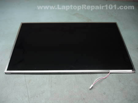
In this guide I will disassemble a laptop LCD screen in order to remove and replace the backlight lamp (CCFL).
Replacing the backlight lamp is not an easy task even for experienced technicians. If you do something wrong you will permanently damage the LCD screen and have to buy a new one. Proceed on your own risk and do not blame me. 🙂
Some recommendations before you start:
1. Work in a clean room. You don’t want dust and lint inside your LCD screen.
2. Make notes, so you know how to assemble your screen back.
3. Take pictures.
4. Before you remove something, take a closer look at the part and memorize how it is assembled.
5. When you are assembling the screen, remove dust and lint with compressed air. Do not use cloth.
The backlight lamp (CCFL) is located inside the LCD screen, so we are going to take it apart. In this article I’m not going to explain how to remove LCD from a laptop, it’s been covered before.
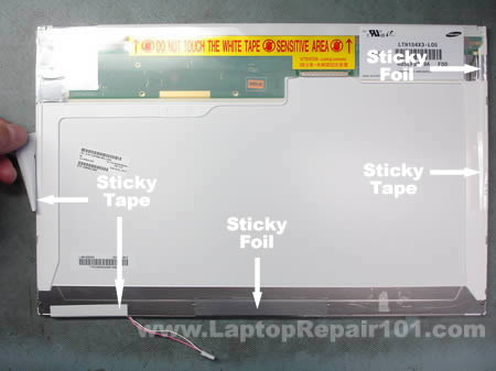
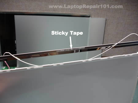
Remove sticky tape and foil from the back of the screen and glue it somewhere so you can reuse it later, when you assemble the screen.
Removing tape from the backlight cables.
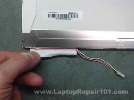
On my screen the green circuit board was glued to the plastic frame with a double sided tape. Carefully unglue the circuit board. Be very careful, do not flex or bend the circuit board.

The circuit board has been unglued.

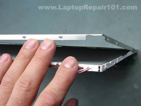
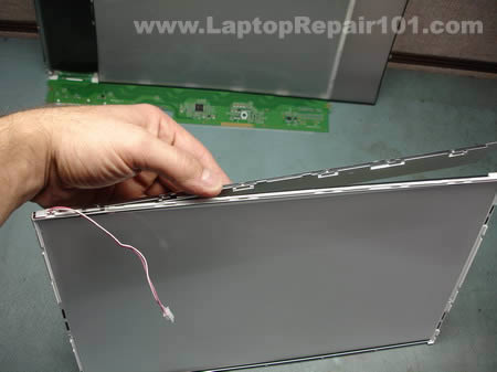
Place the LCD screen on the side and start removing the metal frame witch secures the LCD to the plastic frame. There will be many latches on all sides of the frame, you can unlock them with a small screwdriver.
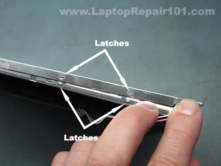
Continue separating the metal frame from the plastic base.
On the following picture you can see that frame, LCD with the circuit board and screen base have been separated. Be careful, do not touch internal components with your fingers. Handle all internal components by the sides.
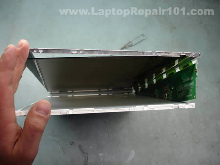
Place the metal frame and LCD with the circuit board aside. You’ll need them only when you assemble everything back together.

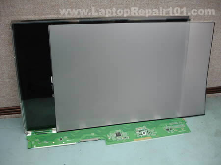
There will be a few transparent layers inside. Carefully remove them from the screen base. Do not separate the layers, just put them aside together.
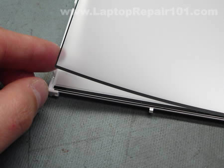
Keep everything organized, so you have no trouble assembling the screen.
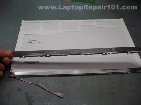
Start removing the metal cover from the backlight lamp (CCFL).
The backlight cover has been removed.
The backlight lamp (CCFL) cables are routed through small plastic hooks.
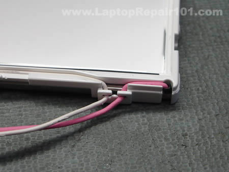
Unroute the backlight lamp cables.

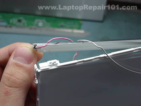
Now probably the hardest part in this disassembly process – removing the backlight lamp and reflector. The backlight lamp is secured inside the reflector so you have to remove both and then separate them.
Before you remove the backlight lamp and reflector take a closer look how it’s assembled and mounted to the screen base. Fitting the backlight and reflector back in place could be a very challenging task.
The reflector is glued to the screen base with a double sided tape.
After the reflector has been unattached from the screen base, you can start removing the backlight lamp. As you see on the picture, I marked the left side of the reflector with a red dot so I know where the red cable goes when I assemble everything back together.
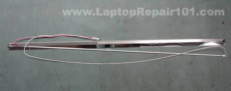
The backlight lamp (CCFL) has been removed from the reflector.
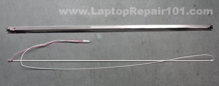
In order to access the backlight lamp leads you’ll have to remove the rubber caps from both side of the lamp. I’m not sure if you can touch the backlight lamp with your fingers, so I would use rubber gloves.
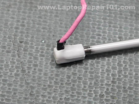
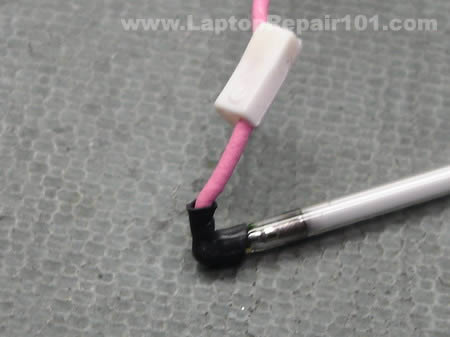
Cabled on both sides of the backlight lamp are soldered to the backlight leads. In order to access the leads you’ll have to remove the black insulator on both side of the lamp.
Unsolder both cables from the old backlight lamp and solder them to a new one.
You can test the new backlight lamp (CCFL) before you install it back into the screen. Connect the backlight lamp into the inverter board and turn on the laptop. The backlight lamp should light up.
From my experience, on some laptops the backlight lamp will not light up until the video cable is connected to the LCD screen. In this case you’ll have to assemble the LCD screen and then test it.

280 Responses
Tony Virnoche
Where id you get the lamp and how much?????
cj2600
Tony Virnoche,
I didn’t replace the CCFL while I was creating the LCD disassembly guide, I just took it apart as an example to show how you can access the backlight lamp.
If you are looking for a new backlight lamp I guess you can buy it through this site. They have a good selection of backlight lamps from $9.99 to $14.99
Allende
Hi,
How can I test inverters in a lab?
I have one notebook with a dark display. How can I know what is bad: the inverter or the backlight?..of course before buying a brand new one.
Can I have a spare backlight just for testing inverters? Are all the inverters compatible with this spare backlight?…What about the connector and the output voltage?
cj2600
Yes, you can. That’s exactly how I test the backlight problem. I have two test backlights with two different inverter connectors, I removed these backlight lamps from broken screens.
When I have to troubleshoot a laptop with backlight problem, I disconnect the screen from the inverter board and connect my known good backlight lamp instead. If my lamp lights up, most likely there is a problems with the customer’s LCD (backlight). If my test backlight lamp doesn’t work, most likely this problem is related to the inverter board (or video cable, motherboard).
This is the only reliable test I know.
I’ve been using my test backlight lamps for a long time with many different laptops and never had a problem. For example, may backlights are for 15″ LCD screens but I also use them for troubleshooting 17″ and 14″ laptops. So, from my experience, any backlight lamp should work fine you just have to have the same connector type for the inverter board.
I don’t know, I never cared about it. 🙂
blackjak
Before my screen went black, i had a big black “stain” on the bottom right corner, like something was burning. The screen was also flickering… and then it turned black….
I ordered a new inverter and tried it right away, but my screen is still black! I noticed that if i look at my screen from an angle with an external light, i can see the icons and everything which probably means that the screen isn’t dead.
Do you think that my problem is the backlight lamp?
thanks!
cj2600
blackjak,
If you installed a known good inverter board and it didn’t fix the problem then most likely you have a problem with the backlight lamp (CCFL).
Your screen was flickering before it went out and usually when it happens it’s either bad inverter or failing backlight lamp.
Unfortunately, the only way diagnose the problem is testing the laptop with another working backlight lamp or LCD screen and see if it lights up.
Just in case you can try reconnecting the video cable on the motherboard, it’s possible that the connection got loose and the inverter board is not getting power from the motherboard.
Also, check the lid close switch (if you have any). Make sure it moves freely. When the lid close switch gets stuck inside the case, usually it happens when it’s dirty, it cuts off power from the inverter board. The laptop “thinks” that the display is closed because the lid close switch is pressed down, as a result the backlight is off.
Nathan
anyone know what the problem is with an lcd that has light but lines int? i dont thint the backlight is faulty as it is bright screen, just lines and odd patterens
the monitor out works ok so i assume the video chip is aok
cheers
nate
cj2600
Nathan,
Do you see lines on the entire screen or just on a part of the screen? Can you see any image on the LCD screen at all?
It’s possible that connection between the video cable and LCD screen or motherboard is loose. Reseating connections on both ends of the video cable might help.
Check out this post: Laptop has bad video on the LCD screen. What is wrong?
Nathan
i cannot see any image, the lines are severe
the lines are rather severe, and it sometimes brighens up to a white screen
gautham
hi guys……i have a mx35s329 purchased in december 2004. luckily it hasn’t given any major problems unitl now.
recently i have observed some screen flicker. the screen sometimes blacks out…….but if i press firmly just beside the “control” key on the left side of the laptop the display comes back on. tapping the computer gently on the right palm rest also brings the display back on. i am thinking its some kind of loose connection, but do not know which wire.
there is a problem with the key board too. some of the keys don’t work. i recently replaced the key board, but broke the clip while inserting the ribbon of the new keyboard. do you guys know if the key board clip can be replaced.
past service history includes a FL inverter replacement and ac adapter replacement.
i have had no problems with respect to heating shut downs, charging the battery, dc connector pin and system crashes.
hope you guys can help out.
cj2600
Nathan,
sounds like a problem wiht the LCD screen.
You’ll find more tips for troubleshooting bad images on LCD in this post:
Laptop has bad video on the LCD screen. What is wrong?
By the way, did you test the laptop with an external monitor? Video on the external monitor is fine?
Seramar
Forgive me if you mentioned this elsewhere or another reader already asked but when testing the backlight as you do on this post and troubleshooting-laptop-with-backlight-failure must you use the backlight specific to the model you are working on or can you use any backlight? We have plenty of working, spare backlights available at the shop where I work but not necessarily all of the models we use regularly.
Thanks 🙂
cj2600
Seramar,
I think for test purposes you can use any working backlight lamp.
I have only two working backlights with different connectors for the inverter board and I use these backlights all the time. I’ve been using my lamps with many different laptops (with different LCD sizes) and never had any problem.
Computer Repair Guy
Very helpful website. A good resource for end users and no doubt some professionals as well.
d santonia
thank you! the warranty on my son’s computer ran out in nov.
using your directions he replaced the backlight lamp.
Mohd Nayeem
Excllent Guide to Replace the FLOROSENT LAMP.
Thanx a lot……..
Aparna
Can you tell me, where to look for the CCFL backlight. Apparently no one in Bangalore, kolkata, India stores these backlights.
jason
i recently replace my backlight, but in the process i dirty up the optical layer that spread the backlight, can i clean it, if i can how.. and if i can’t where can i get a new optical layer.
loop
Very comprehensive guide… I’m thinking about changing my ccfl too, although it hasn’t conked out yet, but it has become rather dim over time.
Thx to this guide I might give it a try.
Haluk testereci
Since Toshiba claimed they can just change whole LCD instead of backlight bulb and asking US$ 702, you see right US$ 702 for LCD panel…SO i have nothing to loose other than try above replacement which gave me courage to do so..Thank you very much for nice detailed work and demo done above…with my best regards
drey
thank you for the instruciton how to replace the backlight of my laptop, it help me a lot, i appreciate that.
coolerro
do you know at what voltage the backlight lamp works?
Ruben
Hello there,
I have a problem with my laptop, the back light seems likes is not getting electricity from the inverter.
I bought a new CCFL lamp and connected to the Inverter output. When I turn on my computer the lamp turno on for like half a second and then it turn off, and it did that like 3 times, and after that it never turn on again.
So my question will be, is the back light turn on all the time when you connect a new one?
And with the monitor connected, is the lamp turn on always?
Gedas
That helped me to replace backlight for my old laptop. Thanks a lot.
Wayne Reep
I’ve already removed the ccfl but cannot find where to buy a new one. I have a Toshiba satelite bought in 2005.
Anthony
How can I find out the part number for a lamp for Fulitsu Lifebook C2210? This is a 15 inch screen and has a Cold Cathode Fluorescent Lamp. The part number for the screen is LTM15C460F (or CP121857-02)……Thanks
Steve Yaroscak IV
Hello. Looks like you’d be the one to ask about this.
I’ve only looked at your bit on how to replace a ccfl
and to reach it to do so. My problem however is that
everything seems to be working great I just can’t see
anything on the screen that is working because obviously
the bulbs out. I took everything apart and ordered a new
lamp on EBAY but after soldering and testing it as you show,
the damn thing isn’t doing anything. The laptop is a Gateway
4542GP. And it is my parents. I used it for a week and it’s
my ass if I don’t fix this sucker! How can I test the bulb W/O
the inverter? I don’t have a voltmeter well it’s not working
itself so I’m kinda screwed as far as testing that right? The
voltage required for the bulb is A/C right? Please Help!!!!!!!
cj2600
Anthony,
Search on Google for companies selling CCFL lamps for laptops, here’s one: lcdparts.net
After that contact them and explain what you are looking for. Most likely they will help you to find CCFL for your screen.
cj2600
Steve Yaroscak IV,
Can you see a very dim image on the screen? Any image at all? Did you try replacing inverter before replacing backlight lamp?
When the backlight stops working I usually follow these steps:
1. Check the lid close switch to make sure it’s not stuck inside the laptop case cutting off power from the inverter board.
2. Reseat cables on both ends of the inverter board.
3. Replace inverter board.
4. Finally replace the LCD screen. I do not replace CCFL lamps for my customers, I do it only on my own laptops. It’s very time consuming repair.
Dexter
I have a LCD which is built and looks exactly like the one above. (do they all look the same?????)
My problem is that I have a horizontal line running across the screen.
I dismantled the LDC, but it seems that the LCD has leaked (?) at the edge where these lines appear. Can this be correct ? I can send you some pictures if I have your mail id.
Any help appreciated.
Thanks.
cj2600
Dexter,
I don’t think that you cannot fix it. If the LCD screen has been damaged you’ll have to replace the whole screen.
julia howard
I should be very grateful if you could inform me as to whether cold cathode fluorescent lights (CCFLs) used as LCD backlights use a radioactive material which emits beta particles to start the ionization of the gas unlike the hot fluorescent lamps where the cathode is explicitly heated in order to excite the electrons causing their emission.
This question is prompted by the Wikipedia article on CCFLs which stated that CCFLs may contain a source of beta radiation in order to start the ionization process.
As our computer monitor is placed on the only table in the house, use of the table for other purposes means that I have to face the back of the monitor where the backlight can be seen through the grill.
Looking forward to your response,
Yours faithfully,
Julia Howard
johan vall
i have a similiar problem with my screen where i need to use a flashlight to see the screen . i havent gotten as far as replacing the inverter or the bulb. My question is that whenever i open the lid i hear a little buzzing sound from the base of the screen . could that be a bad connection could it be the bulb trying to turn on ?or have i just never noticed this sound before? its very low.
burning D510m
I have the same problem as blackjack (posted on 2008 jan 12) on a Dell D510m. Besides the flickering and dim lcd problems, I also noticed that the bottom left corner of my screen started BURNING/MELTING and caused some pixels to turn black, while the baclight was working at maximum brightness. When the backlight went completely off, I replaced the inverter and the problem remained. But having disassembled the bezel, I could finally notice SPARKS coming from inside the ccfl casing.
Before going further in my repair process, does anyone know if a faulty CCFL can cause overheating, or is it just a bad connector, and can it cause the inverter to die ?
Thanks for the guide.
burning D510m
update.
My problem was due to a soldering defect from the manufacturer. I suppose that the high voltage combined with a tight environment started to weaken the rubber pin around the cathode. Once the rubber pin altered, the problem intensified so that it caused some plastic parts to melt, especially one of the corners of the thick reflector layer, and weakened the CCFL glass/electrode (heat effect probably). Hopefully, the LCD matrix wasn’t affected.
This is a fire hazard Dell and all CCFL based manufacturers should reconsider seriously !
Charles Zaffery
I just replaced a CCFL for my laptop, an Acer Travelmate. I bought a new LCD because mine was dropped by my younger brother and cracked in several places. I got a good deal, but as it turns out, good deals come with a price. The LCD had a burnt out backlight.
I skipped almost all of these steps because I live in a house with pets and children. Not wanting to contaminate the inside slices I took out the backlight from my old LCD, just tore the whole damn thing apart. It was a 2″ wide assembly that ran across the bottom of the LCD.
I then proceeded to bend the metal of the new one (very risky, I know, but if I didn’t take it out this way it would’ve never worked again, something would have broke).
I used 2 eye glass screwdrivers to get the bottom layer set into the unit so that it could provide proper light to the whole thing.
Bent the metal back into place, plugged everything in, works like a charm. It is a tad too bright in the left/right corners but I’m not worried about it as it works and that’s what matters more then anything.
I also wouldn’t recommend ANYONE DO IT THIS WAY. DO IT THE RIGHT WAY UNLESS YOU ABSOLUTELY HAVE NO CHOICE.
mindy j gowins
what is the normal cost to repair the back light if I took it in for repair
George
What is the VOLTAGE GOING to the Pink and White Cables AFTER the Inverter? If I had a power supply to test the bulb directly what would i use?
Ahmet
I have tried replacng the LCD still got the dark screen and went ahead replaced inverter itself and the inverter with the cables, still have the dark screen..What is the las step? I have replaced the LCD but did not work..Do you think it is the main signal cable????
cj2600
Ahmet,
You said that you replace the inverter with the cables. Did you mean the video cable?
First of all, I assume that all new parts you installed are in a good working condition. If you replaced the LCD screen, inverter and video cable but still experience the same problem (very dark image on the screen), apparently that’s related to the motherboard. I don’t know what else can cause this problem. I’ve seen that before but it’s not very common. In most cases replacing the inverter board and LCD screen after that fixes the issue.
By the way, check the lid close switch – a small button located close to one of the hinges. Make sure the close switch moves freely and is not stuck inside the laptop case. When you press on the lid close switch it cuts off power from the inverter board (and backlight lamp). A dirty switch may stuck inside the laptop case and because of that the laptop “thinks” that the switch is pressed down. In this case there is no power coming to the inverter/backlight lamp and the screen remains very dark even after the laptop is turned on.
Ahmet
I have replaced the inverter with its own cables not the video cable. I meant the inverter board and the cables that go into the inverter.
When I replaced the LCD, unfortunately I purchased the wrong model but it did still work. the cables weren’t the same as in the new lcd but the screen did show that black screen again.
I haven’t tried to change the video cable itself. Now it is the turn to replace the CCFL tube but it looks complicated. And after you said it may be the motherboard, I even thought that it is not worth the time I put into repairing it. I should have just sold the damn thing and got a new cheap laptop. well, well…we’ll see if I can do this tube replacement..
M Neher
I just replaced the inverter and still have the dark screen, very faint image. Before I tackle the backlight replacement I have a quick question, I bought the laptop as a gift and immediately had to wipe Vista and installed Windows XP, could I be having a driver related problem? The screen went dark just a couple of months after I changed the OS.
cj2600
M Neher,
No, this is not a driver related problem. This problem could be related to the backlight lamp, video cable or motherboard.
Check out this post: Troubleshooting laptop with backlight failure
You may find some useful information in there.
By the way, you can find a new backlight on ebay for around $15. You can find one with wires already attached to it, so you can plug it into the inverter and test before you open up the LCD screen.
Eric
I am interested in replacing my 15.4″ WXGA with any of the following: WSXGA, WXGA+ or WUXGA
my question is, are lcd connections to the inverter and the motherboard standardized? are the lcd panels themselves standardized as well, i.e. are all 15.4″ laptop panels created with equal dimensions?
Jason
Hi, I just got a free laptop that isn;t working, it boots and runs fine with external monitor, but the laptop monitor remains dark and there is a LOT of heat where the LCD cable plugs into the motherboard. The screen flickers once when initially powered on and thats it. Bought a new LCD cable, and it does the same thing. Does this sound like a backlight, LCD inverter, or a motherboard problem?
Thanks for your help and the great article!
sharky
I have replaced both an inverter and the screen with a working backlight, still see a dim screen. Spent hours stripping the laptop and checking for any lose cables to no avail. Anyone any ideas?
PACKARD BELL E6310? My only guess could be the inverter which i bought of ebay is faulty or the videocable is faulty or even the motherboard….please help anyone
$p!k¥
hi, i dropped my asus f3sc and it broke at the hinge. i was too stubborn and continued to use it till one day, the grease dried up cos it had been exposed to the open air for far too long, then when i was opening my notebook, a couple of the wires connecting the LCD to the base came out and i lost my screen… just the backlight because the webcam still works. i can still see images when i turn it on but i have to tilt it towards light… cant do any bios operations anymore, etc. PLEASE PLEASE PLEASE PLEASE SOMEBODY HELP ME>>> I NEED HEEEEEEEEELLLLLLLLLPPPPPPP. how do i fix it???????
Larry
I have a Toshiba 5205-S503 with a LCD backlight bulb that out. I attempted to replace the BLB but I basically destroyed those little rubber connectors that cover the solder connections. I attempted to cover the solder connections with one wrap of black electrical tape and reinstalled. The monitor worked beautifullly for about 20 seconds, then there was a high pitched sound and the monitor went out again. I figure maybe it the connecting wires got shorted. I have an extra back light bulb. Any suggestions for how to reinstall without those tiny little rubber booties? Thanks!
Jim
If you are talking about the black rubber booties, that is simply heat shrink tubing which you can buy at an electronics store, or a home improvent store.
Larry
Jim,
That heat shrink tubing did the trick! Thanks so much for your tip. It enabled me to repair my LCD screen with a new $8.00 back light bulb instead of hundreds of dollars for a new LCD screen.
Ricky
Thanks for the write ups. My Gateway 7405 GX screen went black. I followed your instructions and got it working again. I was not able to test different parts without buying them but it was a small investment. I started with the inverter, 15.00 off ebay, didn’t fix it. Next I bought a inverter harness, only because it was cheap (4.00 shipped) and I was hopeful, didn’t fix it. So I figured it had to be the ccfl bulb. I didn’t want to tear into it until I had one so I ordered one again from ebay (20.00). I tore into it and when I finally got the bulb out I found one of the wires broken at the solder joint. I fixed it, tested it and it worked. 40.00 is a cheap investment considering what a repair company would have charged me plus the wait and I was still able to use my laptop by just plugging in another monitor. Changing the bulb is not for the faint of heart or unskilled. I consider myself pretty good and it was tedious!
Thanks Again!
John
i got all the part how to replace the backlight. However i forgot the type of tape that use for my Dell Inspiron laptop. Is it a copper tape or a normal tape ?
Vanderley Pimenta
Hello I am Brazilian know little English but always seek the information which emerged in informatics and with that you solved my problem. thank you so
Manfred
I have an IBM ThinkPag T40. The backlight went off about 3 seconds after boot. Using a flashlight I could see the dark screen content. I logged in. Using a Linux command I turned the LCD screen off (like screen off on idle). Then moving the mouse the screen became alive again, just for a few seconds before the screen went dark again. I can repeatedly “activate” the backlight for a few seconds by turning it off and then on again. But it always stays on only for a few seconds. If I reduce my screen backlight intensity (reduce brightness of screen), then the screen stays on longer.
I wanted to determine if it is the inverter or the CCFL backlight that is bad. I open my ThinkPad and a second laptop I have at home. Then I connected the ThinkPad inverter to the CCFL cable of my other laptop. The CCFL backlight stayed on on my other laptop indefinitely, i.e. for ever. I thereby determined that the broken part is the CCFL lamp, and that the inverter is good.
I hope this comment helps someone else with the same problem who wants to determine if the inverter or the CCFL backlight bulp is bad.
Phil
I have replaced the inverter on my Tecra A1. Twice. The screen is still dark. Where is the switch located? Sorry for the dumb question. Your website has been very helpful in the repair of this laptop. Thanks.
Armando
Hi. Very good explanation on how to replace de CCFL backlight.
BUT … I broke the panel.
WARNING !!!. This is a very difficult procedure. When you reassemble the panel, the pieces will not fit easily.
My suggestion: practice with a broken panel first.
If you are not very skilled (you need excellent eyesight too) consider buying a refurbished panel.
BitFlipper
Hello,
great instructions, but was this for Dell E1705 or 9400? the screen wiring/areas looks the same. I have a E1705 with backlights going bad, I read on line saying for this type of screen it contains two CCFLs, so I bought two of them, but has not yet taken it apart to replace them as I have not seen anywhere how to replace both bulbs. Any help is appreciated.
Brian
i wondered if the ONLY way to take the wires out of the old backlight, and put it in the new backlight, is to solder the black insulator? Thanks for the help.
Waleed
I really enjoyed your repair tips on laptop and I have a question for you. I have this lab top, kind of old one but very good one. it is dell insipiron. it takes a long time to work when I hock it to the power adaptor. it is not the adaptor, it is the main power board inside. I pust the power button and it starts then seconds later, it shouts down again. some time it works after a number of shutting down but very often that it does not work. any ideas. thanks
cj2600
Waleed,Do you have to move or adjust the power adapter inside the power connector in order to make it work? I’m thinking maybe you have a problem with the power jack and it has to be resoldered?
mmtechnical
This is a very detailed SWI on screen repair. I really appreciate you taking the time to document this….Many thanks.
Backpacks
Hello, I was wondering if you could help me with information on where to buy a backlight for a Toshiba Portege M200.
Site or store will help greatly!
please email me back.
-backpacks.
Budget Barry
Thanks for all of the tips.
I managed to replace the tube in my 12 LCD TV which failed.
I scrounged a tube from a ten year old laptop which has seen its day. Tube was about a cm too long but works well enough with the end poking out from the wire slots.
I managed the job without the screen separations. Just removed the narrow metal shield behind the tube and got the replacement in with a little effort.
ira
Just wanted to say that this website is awesome. wish i found it years (and several laptops) ago.
Magoo
Thanks for helpfull tips. My son’s t43 had the black (very dim) screen. I diagnosed (guessed) it was the back light. I ordered one from lcdparts.com and when I went to checkout I found I had a free $20 credit from Paypal for some promotion or something. With S&H the parts cost was $19.97. Got the parts for FREE! + 3 cents profit. Thank you Paypal.
Seriously, this was a pretty complicated hardware job. The hardest part was getting all the tape off. Also 30 or 40 very tiny screws and a very confusing mess of arranging all the various layers, brackets and plugs in there. And of course the extremely fragile looking bulb about the size (and strength) of stick of dry spahgetti. Plus I am not very good at soldering.
Anyway I got it done. And it actually worked. Hey your screen is useless as it is so what do you have to lose? $20?
Tool notes; In addition to a soldering iron usefull tools are a jewelers screwdriver set, tweezers, guitar pick (for prying without marking) and a magnifying glass.
Job note; I didn’t worry about fingerprints or dust or touching stuff. On the reassembly I left off all of the tape and several of the screws. Just because they are ‘engineers’ does not mean they know what they are doing. After all, that soldered in (not pluged in) bulb is not considered a FRU (field replaceable unit) by the geniuses who designed it.
I guess we know better!
Good luck!
Magoo
Oh one other thing. On the t43 you can leave the screen lid attached to the keyboard base. You just remove the screws holding down the bezel and then pry the bezel off. Then you can remove the lcd assembly and start disecting it till you get to the bulb.
Bob Nielsen
I replaced the back light and inverter in my T40. Not for the faint of heart. Turns out I didn’t need to replace the bulb–just a bad (broken) connection. I broke the cable to the little light on the top of the panel—never use it. I hope to get a few more hours out of the old T40–everyone tells me I should get an Apple. Thanks.
B Templeton
Thanks for such a helpful and amazing site. I’m currently juggling 2 Ibm a31p Thinkpads that are dying a slow and painful (esp. for me!) death and your knowledge has given me a lot of insight of where to go from here.
Happy New Year and keep up the good work!!!
BENJY
Scooter
What is the lowest, mid, and highest I could expect to pay someone to replace a backlight for me.
jakk
Please can some hi tech dude help….
I have dark screen on an acer aspire 2920, I have tested back light and inverter and vga cable and cant see any damage to pins on the motherboard, it’s not the switch as it’s magnetic and I tested this, can I solder form the dc socket or motherboard to power the inverter with a new cable ?????
Rey
I have an HP Pavillion zv6000 laptop and my daughter rubbed a magnet on the LCD screen. The screen is now black and you can faintly see the image of what you are working on. I am able to get video when I hook up the laptop to a monitor. Can you tell me what went bad and needs to be replaced, the LCD screen or the inverter board?
eknetizen
My laptop display comes on initially but pretty consistantly turns of within a second or two, and I can repeat it with shut&open of the lid. I opened the lcd and pulled out the inverter and the backlight and fixed a wire that seems to have broken (I think it may have been on the verge and while I am trying to open the lcd it may have lost its last leg). So I thought my problem is that loose connection and so fixed the broken wire, and connected the inverter and backlight (just outside – without actually mounting them back in their place within lcd), it didn’t turn on at first, but then I connected the video cable, and sure enough the backlight came on this time, and also stayed on (I waited over a minute to make sure it stays). So, there I was all excited that I fixed the backlight with just a wire patch, but then after I mounted everything in place and tested, I am back to it turning off promptly within couple of seconds.
Anyone can help me figure whats up with this backlight working fine when its outside the mounting, but turning off within a couple of seconds when its in the mounting? I don’t believe its lose connection because of its consistancy, so Is there some safety shutoff or something thats getting triggered only when its fully assembled? thanks in advance for the help.
cj2600
eknetizen,
Maybe it’s just a bad inverter board? It looks like you didn’t test the backlight lamp and inverter outside the case for a long time. I think one minute is not enough to jump to a conclusion that it works fine outside the case.
stuart mitchell
I have a dell vostro 1000 and part of my screen has dimmed (bottom left corner, making it very hard to view anything in that area) whereas the rest of my screen is fine and crystal clear. Is this a screen inverter problem or a backlight lamp problem? or something else entirely?
stuart mitchell
EDIT from post #78 as i cannot edit that post specifically
the dimness has now turned into a red dimness from top to bottom on the left hand side of my laptop, im starting to think its the backlight lamp thats at fault but could someone confirm it (based on information ive given)
Joe Mason
Your instructions were very helpful. They enabled me to replace the the backlight on my son’s Dell laptop. Thanks a lot.
Kelsey G.
Question:
I have a HP Pavilion zv 6000
my back light comes on for 1 min and statrs to flashing off & on then goes dark. Does a replacement LCD screen come with the back light built in it ? Wll this fix the problem? Replacing the LCD screen looks less complicated.
Thanks
KG
Abraham
hey, im haveing problems becuase i was trying to charge my laptop and i dropped it and busted the part you charge the laptop at how would I fix that?
Marco
Tried it, purchased the lamp $14, disassembled LCD panel, unsolder-ed/re-soldered lamp, but while reassembling the sandwich the LCD fell apart and ripped a fragile ribbon cable, that became unrepairable… proving to me the whole repair process is worthless… The odds of a successful repair are 50/50 at best, which was my impression before beginning the repair process.
The FRU should be the LCD panel assembly. If Dell will not sell it as a FRU, then phuck Dell, I’ll purchase future laptops from another vendor…
Of all our Laptops at our small company, I’ve had three different Dell laptop that have lamp failures vs. none from laptops purchased from Sony, HP & Toshiba. Currently Dell’s QC of Laptops & Desktop has nosed dived… Dell is no longer my current computer vendor…
Jeremy
First, this website is great. Very informative and having the pictures to walk through the process is great. Thanks for the help.
I had the famous flickering screen which ultimately left me with nothing visible on screen but visible with a flashlight. I’m able to use my TV’s S-video connection to see the computer, but I was trying to repair it myself. I started with the inverter, but that didn’t do anything. When I opened up the LCD screen to change the backlight bulb, I noticed that one of the wires that runs from the bulb into the inverter was completely charred and black. Obviously, I’m assuming this is the culprit behind my problem. I purchased a replacement lamp & wire harness off ebay (bad idea?) and was just testing it before I closed everything up, and was disappointed to see that the new bulb doesn’t light up either. I even tried my old inverter and had no luck. Any ideas what to do next?
My laptop is so old that I’m really just looking to salvage files off of the hard drive, but to complicate matters, I seem to have gotten a virus that won’t let me get past the loading of windows. (says something about RUNDLL Error “The specified module could not be found.) I was going to try and boot in safe mode, but I can’t see safe mode on my TV with the S-video connection. Doesn’t seem to work. Any ideas would be greatly appreciated. Thanks again!
Mark
This repair DOES work. but you need to work slowly and carefully…
Also on some LCDs (samsung for example) you can remove
the lamp without removing the header board first.. That makes it a whole lot easier and less risky.
cj2600
Jeremy,
In some laptops the backlight will light up only when the video cable is plugged into the LCD screen. So, plug the video cable into the screen but do not connect the cable coming from the backlight lamp. Plug in the new backlight lamp instead. Will it light up this way.
There is an easier way to access files on the hard drive. Remove the hard drive and install it into an external USB enclosure ($10-20 in a local computer store). You’ll see an example here:
Accessing notebook hard drive using USB enclosure
After that connect this enclosure to any other working computer and the drive will pop up in My Computer. Access and back up all personal files.
Larry Fostano
I have a question for you that I hope you can answer or help me with.I have a Gateway 7326GZ Laptop with wireless,3.06Ghz processor and 512 memory.I purchased this unit used,it had a problem with the dc power jack and made a repair to it.It worked for awhile but soon died again.I decided that enough was enough so I purchased a new motherboard online, when I installed it and applied power to it ,it seemed to work properly but then I noticed if I were to power down and then turn it back on from the power button it would not power up.Disgusted I removed all power , powered it up again 30 to 45 minutes later and it worked .This is still the case ,if I leave the batter in it it will not start either.I sent the board back and during the transit they sent me another board.nice people. I installed it and still have the same problem, any ideas? Please help
cj2600
Larry Fostano,
Hmmmm.., that’s a very strange failure. Sounds like a problem with the motherboard, but you experiencing the same problem with two different boards, apparently it’s not the board.
Did you test the power adapter? Make sure it outputs correct voltage.
Can you test the board outside the laptop case? All you need is motherboard, CPU, memory. Connect all together outside the laptop case, plug it the AC adapter and test again. Does it still fail?
Troels Østeraa
Hi,
I really appreciate that someone did put all this work into making these guide – compared to how many laptops are sold, there is going to be lots of need, and especially in the future with more dying CCFLs.
Question: What actually results in light leakage from the sides, i.e. why is black sometimes not homogenously black at the sides? From what i see in you dissassemblies, there are no reflectors or any sort in the sides or top, so where is this primary misallignment issue happening that makes these leakages occur?
Would it be possible to readjust by disassembling the LCD? This would seriously be a really interesting article i think 🙂
cj2600
Troels Østeraa,
I’m not sure what’s causing that light leakage.
The backlight lamp is mounted inside the reflector. I’m removing the backlight lamp from the reflector on the picture 18. The reflector is attached to a 2 mm thick glass sheet and the light travels through that sheet. Apparently, in your case the reflector is not making good contact with the glass sheet on both sides. This is just a guess.
I don’t know. I’ve never done it myself.
shuaib ur rahman
thanks alots……..
nice sharing and supports
ken
Can anybody how distinguish which end is the (+)positive and (-)negative end of the CCFL lamp???
The CCFL lamp I have is the 2.0mmx370mm; and both end has no marking in them to help specify which is the (+)positive and (-)negative end.
Which end is for the shorter wire???
I would highly appreciated in advance.
jumpslot
I recently (last summer) bought a sony vaio cr320e laptop. It fell off of my couch and started displaying what seems to be the symptoms of a broken backlight (i.e. see the screen working but the whole thing is dark). I have looked all over the web for sony components so I can replace it myself without spending 500 dollars at the store where I bought it. I was wondering if you can buy a generic ccfl of the same size and diameter as what is installed and have it still work; or is the ccfl manufacturer specific. It appears to me that the real control is in the inverter and the ccfl just puts off light from the voltage produced. any help is greatly appreciated.
newbie
Is this for all laptops? I have an Inspiron 9100 and I am not sure if it is the same. I’d appreciate it if someone would reply ASAP. Thanks.
siraj
good helping this site for like me (laptop technitions)
Rob
For you people doing this, make sure you preserve the rubber insulators and install them cleanly on the new tube the same way they were on the old one.
The reason for this is the backlamps and their wires have a couple THOUSAND volts pumping through them and you need good insulation to hold back the lightning. A couple wraps of electrical tape will NOT work.
The small black plasticy insulation over the solder is heat shrink tubing, available at an electronics supply store.
The fat rubbery molded slip-on pieces that go over the heat shrink are silicone, rated for thousands of volts, and are the REAL insulators. Be gentle with these, do not cut or damage them.
Monisys sells a kit that contains the foil tape and extra silicone boots if you accidentally wreck them. Just be patient and careful.
Michael
What’s your take on this, I have a Presario V2000 no backlight. So I ordered a inverter wasn’t the right model, screw holes were in the wrong place but I hooked it up and it didn’t work. Ordered from another company got one with the exact numbers as the one taken out, the light flashes only on the end with the pink wire for a split sec. and that’s it so it doesn’t work, the company sends out another one and it doesn’t do anything. So I ordered a new light, it didn’t fix the problem, then I ordered a new cable and that didn’t fix it either. I can see the system boot and everything in the LCD and with a external monitor connected. I even tried a few other lights I have. and with the one inverter they all do the same thing flash or nothing. Also the 2 with the exact part number have a blue LED that lights up after getting to the windows boot screen. Logic is telling me I have 4 bad inverters, I just don’t want to believe my luck is that bad. could it be some type of voltage issue with the lights?
KDL
I replaced the inverter and the CCFL on my hp pavilion zv5000.
Now, the screen is still dark, except for a light band across the bottom, lighting up the “tray” area.
Does this suggest an error in installing or reassembling the LCD?
mgriz
have the same prob as 99, everything worked like the guide says except its bright at the bottom and dims towards the top. Im going to try to redo it and make a better connection to the 2mm thick glass(?) and see what happens but does anyone know if maybe there’s another reason…thanks again for this guide and thanks in advance for a solution….please help im sure someone will come up with this problem also
cj2600
KDL,
What was the original problem? Why did you replace both parts at the same time? Will it fail the same way even if you install the old inverter back into the laptop?
james
so i have a toshiba a105 series and im trying to replace my backlight i was going through the tutorial step by step nearing the disassembly of the backlight all i needed to do is take the screen out of its frame. but i read a little further and said that soldering is needed. i was hoping that this isnt true for my model sincei dont have a soldering kit available.
TechShui
James wrote:
so i have a toshiba a105 series and im trying to replace my backlight i was going through the tutorial step by step nearing the disassembly of the backlight all i needed to do is take the screen out of its frame. but i read a little further and said that soldering is needed. i was hoping that this isnt true for my model sincei dont have a soldering kit available.
James, It depends where and how you got the new backlight. I try to get mine with the pink and black cables already soldered on, sometimes I have to take one from a cracked LCD that has a working backlight.
Most online dealers will send you just the lamp, no pick & black cables, so in that case you would have to solder. You’d also have to solder if the cable connectors don’t match (which very rarely happens).
A 15-watt soldering gun costs only $10 at Radio Shack.
james
alright thanks. yeah the backlight that i got didnt come with any cables it was only the bulb. thanks for the tip.
rsaranglao
Hi !
What’s the steps after resoldering the new backlight wires to assemble back the lcd. Do you mount the backlight housing first before you put back the meatl frame and the LCD Glass/ white board / Please advise.
Thanks you.
cj2600
rsaranglao,
Yes, first you install the backlight lamp back into the housing and after that you install all glass layers.
Don’t you remember how you took it apart?
james
so i have a question. i reinstalled my new backlight and everything seems fine. but now my screen has a slight blue hue to it which im assuming that it is the light. i was wondering if there is anything like a break in period in which maybe the light will being to turn white so i dont have a blue hue anymore?
cj2600
james,
I’m not sure what’s going on. I don’t think your problem is related to the backlight lamp you just installed. If it works, it works.
Maybe the video cable is not making good connection with the motherboard? Try reconnecting the cable.
Son1
How do I determine if the LCD, bulb or invertor is the problem in a Dell Inspiron 3800? The LCD comes on at startup and stays on for about 5minutes and then starts to have like a rippling effect starting the upper right corner working diagonally across and then will go black, works on a monitor fine, and always comes on at startup. What is your best guess or recommendation?
Thanks
cj2600
Son1,
Your description doesn’t sound like a problem with the inverter board or backlight lamp. When the inverter board or backlight lamp fails, the light turns off on the entire screen at the same time. I think you have a problem with the LCD screen.
Steve
I have a Gateway 7330GZ, sometimes my screen goes out when I am using it. Then if I move screen it will come on, sometimes I have to find just the right position to keep it on. Could this be something loose, broken wire or dirt? Thanks Steve
james
hi,
may i ask how can i determine which part of the lcd that must be replaced? Actually, the screen is a bit faded and cannot show jpeg files clearly (right now its like viewing negatives from a film) BUT surprisingly, I can still use it for emails and other written stuffs.
Any idea what part that needs to be replaced? I’ve asked a technician about it but said I have to replace the lcd already which would cost me. And in addition, I dont trust any technician these days…
Btw, Im using an ASUS x51r with a defective lcd right now. and can still read things well except in viewing photos.
Tristan
Any idea how you would replace a led backlit screen?
Drew
Thank you. This tutorial was a huge help. I was working on a friends laptop that had a screen with heavy damage (imagine a laptop that looked like it had been hit with a baseball bat) but lit up just fine. I had a replacement screen that was in perfect shape, but was really dim. Using this I was able to switch the backlights and get his computer working.
UTAH
arrrgghhh… I took my tosh satellite sp10-304 to bits to try and fix a problem with the wireless switch and when i put it back together it would not work so dismantled it again to make sure that all was connected properly and yes call me stupid but somehow the processor was not seated correctly and a couple of pins were bent… I straightened these out and seated it and put the laptop back together. all worked apart from screen was really dark – ok so i thought new inverter – £15 off eBay and it still did not fix it – ok so I thought back light – took a m40x equium to bits and tested the light on the sp10-304 – not working – so I think ok I either have 3 inverters and 2 back lights that don’t work or something else is wrong.
I tested all three inverters and one backlight on another laptop and all is fine so I am now guessing I need a new graphics cable for a tosh satellite sp10-304 as I believe that there is nothing going from the MB to the inverter and as it states some backlights will not work unless the graphics cables are connected… or would it be something else?
MOHAMMED NAGDEE
Hello.
Thanks for the great tutorial. I noticed that you dismantle the entire lcd itself. My lcd works perfectly fine except that i have a crack that seems to be on the outermost layer which i think is called a polarizing filter. Is there anywhere that i may get a replacement for a vaio FZ11Z?
Many Thanks
cj2600
MOHAMMED NAGDEE,
I guess you’ll have to replace the whole screen.
jim
thanks very much for puting this information on the web
i new my backlight was faulty but didnot know how to take the screen apart
so i went on the web
and typed laptop backlight help
and to my suprise found your help
computer working great
thanks many thanks
UTAH
I replaced the whole screen and it is still dark… i can faintly see the image but the inverter is not lighting up the back light… i am guessing there is a problem with the board… can this be fixed? whats going on? any help or advice would be greatly appreciated.. thanks
Larry Holmes
UTAH:
Afraid you will have to replace the “inverter” which is the small, slender circuit board which fits under the lcd screen and is accessible from the front of the display by simply removing the trim around the display front. There are instructions here.
One other thing, though: laptops often have magnetic switches which sense when the lid is open or closed. If this switch fails, or the magnet comes loose or somehow becomes weak, the screen will be blanked, or made to go black, by the computer; there is no need to wear out the screen and the battery, by running the screen when the lid is closed.
You will probably find a check box somewhere in your power or other setup menus which will allow you to turn this feature on or off. Turn it off and see if the problem is still there. If that doesn’t help, the above advice stands.
good luck
Larry
Sam
Hello,
Can someone tell me whats wrong with my computer. My processor works but there is no picture on the lcd.
cj2600
Sam,
First of all, you have to test your laptop with an external monitor. Do you have picture on the external monitor?
UTAH
Thanks.. I have replaced the inverter in the screen. i know it works as it has been tested, the same with the backlight…i have two sp10-304 laptops with exactly the same problem… inverters work as do backlights… image is getting onto screen but really dark… its doing my head in….
UTAH
Hi I have tried setting power to never turn off etc… but cannot seem to find anything that will allow me to disable the lid close switch…. could you advise…thanks
Derrick
This procedure requires extra care. The backlight lamp of most LCD’s (I think) contain mercury, which is toxic.
UTAH
Just tested the magnetic switch with a magnet – it goes into hibernation fine but still restarts with dark screen, so if its not the switch, inverter or backlight is my board screwed?
kevin
Hi thanks for ll the great help. I have a packard easy note laptop and screen has gone dark but it still can be seen to be working in correct light. Im going to go about replacing the backlight now. I just want to know if i can use any correct size backlight or are they specific to each model of laptop. In short will any backlight work in any laptop
Fred
Hi Larry,
Thanks for posting the procedure.
I did this to a Gateway laptop with a 15.25 Samsung
screen. As you previously stated:”Replacing the backlight lamp is not an easy task even for experienced technicians” is absolutely true.
This is a very sophisticated repair procedure.
Anyway, the Gateway is back up and running like new.
I chickened out and didn’t un-glue the circuit board as you did but then found it to be that much harder to get the lamp reassembled and reseated but I guess luck was with me that day.
It can be done however, patience, patience, patience!.
I would recommend people buy (2) CCFL tubes when ordering, you’ll only have to pay shipping once.
I had to pay for it twice because I clumsily broke one just after I had soldered it (bummed!)
Thank you again!
Fred
Sean
Hey folks,
My e1705 died last Sunday – was happily watching a video, then there was a fizzle, and then a black backlit screen. I took the whole thing apart, messed with it, gave up and put it back together – then it started working, for whatever reason.
Today (1 week later) it did the same thing again – black screen. I took it apart as the first few instructions show to ensure it wasn’t a loose cable causing the problm, and there’s definitely a glow from the backlight when turned on or fn-f8’ed, but no picture again. Hooking it up to an external monitor allows it to work fine, so it’s not the graphics card (although it was throwing me all sorts of errors until I reinstalled my drivers).
Could anybody confirm that this is an inverter problem? If not, I might just ditch this terrible laptop model and go find something new…
Asidu
Hi,
Thanks for posting the tutorial.
I have just changed the CCFL of an IBMThink Pad R50e for a dark screen as outlined in the tutorial. When I re fixed the LCD Display found that only about 2in of the screen at the base is lighted. The upper part of the screen is still dark. I can see the window screen there but unable to use the screen.
What could have gone wrong in my case?
Garav Kumar
Hi
I have Lenovo 3000 n100 Laptop and my screen was just working fine but one day it was like black, and I just can see a very very very hard to see ghost image on lcd, but when the computer starts it glows fully and in between when I press the Function + f7 key to toggle between LCD and Monitor(which I have connected to laptop for my work) it glows up and in few seconds go away. I am not facing any red tint or hue. what can be the problem??
My external monitor works great with laptop.
I am not gtting what can be the problem. please advise me
Thanks
Gregory
Thanks a ton! I’ve repaired my old Thinkpad T42p yesterday. But for your manual, I don’t think I would ever dare to go that deep.
There are a couple of problems (which have nothing to do with this post), but maye sharing my experience will be helpful for others.
Well, now the screen is kind of blueish/greenish, which I believe is due to poor quality of the lamp itself. I mean it’s temperature is not the same as the original lamp used to have when it was new. So I adjusted screen color settings and now everything looks pretty. Maybe that’ll change over the time. We’ll see. Luckily it’s adjustable. I am not going to edit photoes professionally or anything, so… works for me.
It also seems that I slightly damaged the screen – it now has some very faint blotchiness, size of a quarter, in one part of the screen, but you really have to know where it is to be able to see it.
I also lost 1 screw, although I tried to clean up the area before unscrewing anything. Unfortunately, I didn’t have any spare ones, as I do this kind of repairs maybe once every 3 years. But without this screw, it’ll be fine, I’m sure.
All-in-all, my T(erminator) is alive again and that’s pretty cool!
jacopucci
hi everyone,
i’m having an issue with my fujitsu siemens v3505. basically, the thing was dropped and the backlight lightbulb got smashed. i managed to replace the backlight (HUGE kudos to cj2600) and i suppose i re-assembled it correctly. however, even though the screen works fine now, i’m getting a constant, high-pitched noise coming from the lcd inverter/reflector area (regardless of whether the laptop is plugged in or runs on battery) and the computer slowed down, slightly but noticeably. now, i have no idea what might be the issue – btw, the replacement lightbulb is roughly the same size and circumference as the original one (a few millimetres longer, if anything). would anyone have any ideas as to what to look at/check etc? i’d be really grateful.
cheers
cj2600
jacopucci,
What if you disconnect the video cable from the motherboard and turn on the laptop with an external monitor? Disconnecting the cable will eliminate the display.
If you are getting the same high pitched noise when the display is disconnected, it’s not related to the backlight lamp replacement.
What if you reduce the LCD screen brightness? Will the high-pitched noise go away?
I really doubt that this is related to the backlight lamp replacement. At least I don’t know who these two issues can be connected to each other.
Maybe the backlight lamp is not compatible with the inverter somehow and drawing too much power creating the noise. This is just a guess.
As I said, try reducing the screen brightness and see if the noise goes away.
jacopucci
cj2600,
thanks for your reply, i really appreciate it.
i tried changing brightness levels, but the buzz persisted, changed its tone slightly but at a constant volume.
so i opened the display once again and had another close look at what’s going on inside. i took everything apart up to the point of having a bare lightbulb connected to inverter. at that point, the lightbulb was silent and the inverter was buzzing quietly (it was not the noise that i was looking for, definitely), which i suppose is a normal thing. i started re-assembling the screen, turning the computer on after every step and it turns out that the lightbulb starts buzzing only after i place it in the reflector. btw, the solders are well isolated with caps and tape.
i’m rather puzzled now – what would you make of it? would it be just a matter of fitting the bulb in the reflector? would you be able to give any tips on that, as i have no clue what might have gone wrong?
re computer slowdown, maybe you’re right – it might just be subjective perception (hadn’t used the laptop for a while, so maybe i forgot how slow it was in the first place, lol).
also, i’ll try and dig up the parameters of the inverter and the lightbulb – still, when i was ordering the lightbulb from sparesweb.com, it said that the voltage is dependent on length alone and differences between 2-10mm were irrelevant (the ratio is roughly 1w per 100mm).
cheers
cj2600
jacopucci,
I’m puzzled too. I’m not sure, is it some kind of resonance buzz? Maybe the backlight lamp doesn’t fit into the reflector as it should and it’s touching the reflector?
You might consider buying a brand new LCD screen. You can find it on ebay for less than $80.
jacopucci
hi, you were right about the resonance, spot-on – it turned out that the lightbulb i was fitting didn’t have o-rings on it (why the hell would they sell it like that? =/), so getting a new, proper one (with cables and plug) fixed the problem. and well, i was all cheery and all, re-assembled everything only to eventually discover that the screen wouldn’t light up again, most likely due to what seems to be an inverter failure =(. it never ends! i think i’ve lost my patience and gonna follow your advice about buying a new screen, cause all this screwing/unscrewing/fitting/taping and all has already cost me so much time i really don’t won’t to risk losing any more playing around with those components. eh.
Amanda
Hi,
I just want to thank you from the bottom of my heart! I saved myself over $300 in repair costs on my HP MX3560 Laptop. I purchased the lamp on ebay, and received it 3 days after payment. I pulled this page up and followed it step by step.
I just want to say that this is very tedious work. If you do not have a quiet place to work with a lot of patience please do not atempt until you do. My lamp was an exact match but the little silicone boots that cover the soldering were larger than my original. After carefully trimming then down to size I had no problem putting it all back together.
Good luck to everyone. If you get frustrated just take a break and come back. You will be a lot more focused. 🙂
Rhonda
No offense, but some of you should leave this repair to the pros.
cj2600
Rhonda,
Agree 100%. It’s not easy. Not everyone can get it done successfully.
Craig Hull
Thanks for the infomation and picture it saved me a lot of money
soumya
Thanks a lot…It gives me enough confidence ..It’s just wonderful job,Lovely pictures that clearly understanding
each and every steps.Though it is tough job but u made it
excellent way..
Keep it up..
Again Thanks a lot.
aredant
Thanks for the info. replacement was successful. A few comments – I have a HP DV5000 which is similar to your pics.
As far as touching components, this is only an issue related to static shock. It is best to use a grounding strap when working with any electronics. Static can damage semiconductors. It may not blow them out, but cause them to fail early so watch out. It is caused by your body friction against rough surfaces but dissipates quickly. If you don’t use a grounding strap, try touching a pipe or a chassis frame or something to discharge first before handling components. Holding things by the edges is a good practice but difficult to rely on when trying not to shock electronics.
A fluorescent bulb is OK to touch. It is Halogens that need to be clean because oils left on the surface of the bub can create thermal stress points and shatter the bulb as they get very hot.
My assembly used quite a lot of industrial adhesive tapes but nothing was glued. These can be carefully peeled back but they are sometimes unusable afterward. You can replace them with metal furnace tape and carton packing tapes if necessary.
It is a good idea to replace the inverter at the same time. Although this should not be necessary, mine failed shortly after I replaced the back light bulb. If it is old, the inverter is already weakened. They are inexpensive and will save trouble in the long run.
Jim Hunt
I broke the “Wire” that goes to the Back lite. It dose not look like a copper wire. It looks like it is fabric. What should I do to repair it?
Ima Tool
Thanks for the guide!
As many have mentioned, this isn’t an easy task, make sure you have plenty of room to work, and all the tools you’ll need. For a few of the screws, you’ll need a phillips #000 and be careful not to strip them out.
I just finished replacing my backlight lamp only to discover it was the inverter after all… If you’ll excuse me I’m going to go slam my face against the wall for a while.
Jason Taylor
Regarding the radioactivity question, I am not sure, and was actually hoping someone else would answer, but it would not surprise me if these ccfls are indeed radioactive. They snap apart easily, so this is reason enough for us to not repair them. CHANGING A CCFL IS A DIFFICULT REPAIR. I do not suggest it. Hardest part: keeping the order of all those sheets straight.
cj2600
Jason Taylor,
I agree with your. 🙂
I made this guide almost 2 years ago when one laptop screen would easily cost you $250-300.
These days you can buy some new LCD screens for $70-80. If you can afford that just replace the whole LCD screen.
Replacing the backlight lamp is more fun project.
cj2600
Ima Tool,
If you not sure which one is causing the problem, the inverter board or backlight lamp, go with the inverter replacement first.
Arvind
Hello, I need just a little advice. I have an HP DV5 1011ea and the screen has always been dim on it’s maximum brightness setting compared to my other laptops. I think all DV5 1011ea laptops have this brightness problem and I was wondering if it could be fixed by replacing the backlight? It’s annoying me since I can barely use the laptop properly in daylight even inside the house. Any advice? I was wondering that maybe the screen doesn’t let so much backlight go through it also and if I change both the backlight and LCD scree, would it be of much help? Thanks for any advice!
Ed
I have an IBM Thinkpad. The screen is showing a big black “BLOB” that moves. You can read whats on the screen, if you can read around the “BLOB”. Any idea what’s wrong?? I need to find out the problem before it can be fixed & who can needs to fix it.
Thanks, Ed
cj2600
Arvind,
Have you checked settings in the power management software. Maybe the LCD screen brightness is not set to 100%.
In some laptops you can chance the LCD screen brightness in the BIOS settings. Not sure about your laptop, so go through the BIOS menu.
Have you tried increasing the LCD screen brightness using the keyboard keys? I believe for HP laptop you hold down the Fn key and at the same time press on F10 to increase the brightness.
I don’t think that this is backlight related problem. Sounds more like wrong settings for the LCD screen brightness.
Also, check the latest BIOS update. Maybe it’s a known issue and you can fix it by updating the BIOS.
cj2600
Ed,
Strange failure. Maybe you got some kind of virus?
What if you boot in Safe Mode, the moving blob is still there?
Liezel
hey? i just drop my Dell 1420 and ask for some technicians , there is a display but there is no light, they said my laptop’s problem was LCD LIGHTS. can i just buy any 14.1 lcd lamp? is it differenT?
cj2600
Liezel,
The backlight lamp is mounted inside the LCD screen. It’s very hard to replace the lamp even for an experienced technician. If the lamp is broken, you’ll have to replace the whole LCD screen.
Antonio
I have a Compaq F700 with no image in the screen.
I already have changed the inversor and nothing happen, so I changed the Backlight (It was not easy) and when I power it on I can see the light is working but the screen is nos showing anything, the screen is in black. When I power it on I note a change in the screen color because is black and when I power it on the screen changes to a black but closer to gray.
What is your oppinion? the cable? or I need a new screen?
By the way, If I use the computer with an external monitor it works but not with the screen.
Thank you
cj2600
Antonio,
It’s hard to guess what is causing the problem but from my experience I can tell that LCD failures are more common than video cable failures.
I would probably try replacing the LCD screen first.
Gernot Hassenpflug
Thank you so much. Despite many waits for parts, waits after realization that I need another part, etc., after 4 months I finally fixed my wife’s Toshiba Dynabook DB65C/4RC (not sure model name outside Japan). I went through the process of taking apart the laptop case for the screen area, replacing the rectifier for 15 USD (no change), learning how to take apart the screen enough to get the CCFL and its metal channel out, got a new CCFL for 20 USD, heat shrink tubing for 3 USD, and finally soldered, reinsulated and fitted the stuff bakc together. Really goo screen brightness now in a 9 year old laptop. Thank you!!!
Sue
I recently replaced the backlight for a 15.4 inch screen with a bulb I pulled from a cracked screen. The result is smoky-looking left and right edges on the screen. Realizing this may be an issue with a used bulb, I wonder what your thoughts would be on that.
(I plugged the bulb into the inverter before installing and it burns brightly from end to end).
Also, does anyone know the reason your not supposed to touch the tape at the “sensitive area” on the back of the screen? Try as I might, I always end up putting my fingers on it somewhere! Need some cotton gloves, I guess
Thanks for your instructions, by the way! This is great!
plumboy11
This is great instructions. I successfully replaces a 15″ bulb from a toshiba A85, but there is one minor problem. The screen is now very bright on the bottom and alittle on the dim side on top. Has anyone else ran into this problem? If so let me know. I am sure it has something to do with the reflector piece but I could not see any other way to install it. thanks
tardost
I have a problem laptop screen is dark on the right.
but when pressed on the left down corner lcd back to normal, if released back like that. What should I do thank you
Graham
Thank you so much for this guide! I just finished and the screen looks great! Just a tip for anybody considering trying this, WEAR GLOVES! I thought I would do okay without them, but ended up smudging the thing all up. 🙂
Erik
I just finished the repair and are writing this note from my repaired laptop. Thanks for the great guidance.
I used the repair help on “Troubleshooting laptop with backlight failure” and ordered myself a backlight with cable for the testing and could figure out quickly that the backlight was the problem.
Here are some experiences I would like to share:
1. I placed all the screws on a big sticky tape and put little paper stickers next to it with where they came from. If the location was not obvious I referred back to little sketches that I made with reference points. This was very helpful.
2. I second the recommendation of the gloves. It helps with the electro statics and more importantly you are not smudging anything.
3. Make photos and sketches of each step when you took something apart. This was very helpful in getting the things back together
4. Be very careful with removing the reflector. At the last part that needed to be disassembled I managed to brake the plastic frame at the corner. This is not critical because you can fit everything into the metal frame but it made re-assembly much more difficult.
5. The right tools are important to do the job right. Make sure that you have small screw drivers, a pair of tweezers and soldering equipment.
When I had everything apart, I found out that the problem was a broken soldering point at the backlight lamp. I was able to resolder it. I could push the rubber cover at the end of the lamp back, cut the cable, resoldered and pushed the rubber cap back. I got a backlight lamp with cable which made testing very easy but I could not fit this into my Dell 600m. The cables at both ends have not been soldered with the same angle which made it impossible to fit. I was glad that I could make my old lamp work.
6. Get a lamp without cables for the final replacement and solder them in. (Or one from a better source that fits …)
The job is quite difficult as stated before but it can be done with this good guide, the right tools, good documentation / organization of the disassembly process and PATIENCE. Overall, it took me 3.5 hours but as I said before, I took my time and “over-documented” to make sure that I get it back together. The results prove that I did it right. However, it would have been easier to get a used LCD on ebay for 60 USD. I just did it because my screen was spotless before it broke and I like to work on mechanical things on my cars, watches etc.
Thanks again for this great guide. I would not have been able to do it without it!
reticon
WARNING FRAGILE, FRAGILE, FRAGILE, this CCFL is much more fragile than you’d even think! Obviously it looks fragile but even the pressure to remove the rubber insulator could snap it. My old one showed signs that it might be repairable because there was a short on one end, but just a little scrape trying to get the melted insulator off to make a clean solder point snapped it like a twig. A little more playing with it and it snapped again just with a slight tap from my pinky finger. It’s best that I get a new one anyway cause it was a burned up mess on the end, but learn from this.. FRAGILE! Just assume that a toothpick is about 1000 times stronger.
Tim Adams
Great advice from those that took the time to post their experience.
1. I found that using a razor blade to remove the boot was much safer and easier.
2. Using rubber gloves saved the screens from hand prints.
3. Investing a few dollars more for the repair kit is highly advised.
4. I have found that replacing the screen inverter at the same time will also save you time and money. The root cause for a black screen can be either the CCFL lamp or the inverter. Some would argue this, but without an inverter tester, you won’t know until you replace the bulb.
5. The white tape that keeps the backing secured on the screen does not stick very well once it’s removed, even as careful as you are. Buying a small roll is advised, but not necessary. The kit does not include the white tape.
6. Test the CCFL backlight before you install it back into position. Extreme care when putting the top metal bracket back over the lamp, and most of all, read what the other techs have posted. Use notes, it can be easy to install the the screen upside down. Will that make a difference? I did not find out.
Larry Sabo
Thanks very much for your helpful and clear guide. My first effort was disappointing, as the replacement lamp (pulled from a matching screen) is not as bright as it should be. I also got a few specks of dust on the reflector/screen, thanks to the reflector layers sliding out onto the table during handling. Next time, I think I’ll tape/glue the corners of the reflector layers.I also have a bright band across the bottom, beside the lamp, probably due to not reassembling the lamp/wires in the reflector exactly right. Also, I may design a holder for the LCD, layers, etc., to minimize dust getting onto things and to keep things in correct order/orientation. Next time will be better. Thanks again.
steve
Hi How can i tell if its the back light or the inverter that is the problem? my screen is ok for a few moments and then goes real dark after initial start up and stays that way. please help
Dani
Steve, test the inverter first. Get a new one or a known working one and put it in. Installing a new inverter is much easier. You have to remove the inverter anyway in order to replace the backlight, so might as well replace the inverter first.
I do have my own question. I have to replace the backlight and am thinking of buying a ccfl with the ends already connected because I have no soldering experience. Any foreseeable problems with that approach?
WEBMAN
Nice A very helpful page thanks for the info
Jason Fason
I do not have a solder. So where can I buy a ccfl with the ends already connected?
gfrobe
Hi all. I’ve got a Compaq NX7010 with a flickering screen. I used to be able to tilt the screen a bit and the problem would fix itself but eventually it’s gotten worse. I had a pinched LCD wire and thought that was problem but replacing it did nothing. I then tried changing inverter but again, no luck. I’m assuming I might need to change LCD but am a bit nervous about shelling out the money if that isn’t the problem. I don’t have any pinkish tones and the screen itself, even when flickering, is quite bright so I’m questioning whether the backlight is the problem.
Have hooked the laptop up to an external monitor and all is fine so I’m ruling out the video card.
What say all the experts out there? Does it sound like a new LCD will fix the problem or could it be something else, i.e. maybe connection between motherboard and LCD?
Thanks.
cj2600
gfrobe,
You are correct, if the external video works fine, the problem is not related to the video card.
You’ve done everything correctly and I think replacing the LCD screen would be the next logical step.
I don’t think so. You replaced the video cable and reseated connectors. I don’t think this is connection related issue.
Most likely it’s either bad backlight or failing LCD controller board. In both cases the LCD screen has to be replaced.
cj2600
Jason Fason,
You can search on eBay.
Jean
Hi,
I have an HP DV1016AP laptop that dates back from december 2004.
While it is still running fine, the image is getting uncomfortably dim.
I assume that it may be the backlight bulb getting too old…
what should I look for before spending money to replace this bulb? Could the dimming be caused by something else?
In fact, it is not so dim I cannot work, but dim enough that working in low light conditions, or for long periods of time is uncomfortable.
I noticed this when I worked simultaneously on anoth laptop and noted its display was considerably brighter.
Thanks for your input and advice.
Jean
KiranKumar
Hi, The site is very good.
I am using the HP Pavillion dv2840se laptop from past 2 years. i never face any problem till now.
Two days back I shutdown the laptop normally after my work. After 2 hours I tried to start the laptop but the power button and HP quickplay buttons are not working. So I tried to start the laptop with HP quick play remote. From remote it is starting but my screen is black. I noticed that if i look at my screen from an angle with an external light, I can see the icons and everything. What may be the problem.
Thanks in advance,
Kiran
cj2600
KiranKumar,
It sounds like you might have two different problems.
I’m not sure why the laptop will not turn on when you press on the power button, but turns on from the remote.
Disconnect the AC adapter, remove the battery and wait for a few minutes. Now plug in the AC adapter and try turning it on again. Will it start?
Can you start the laptop with video on the external monitor?
KiranKumar
Hi cj2600, Thanks for reply.
cj2600: Disconnect the AC adapter, remove the battery and wait for a few minutes. Now plug in the AC adapter and try turning it on again. Will it start?
KiranKumar: I tried the same but no luck.
cj2600: Can you start the laptop with video on the external monitor?
KiranKumar: When I connect the laptop to external monitor it is working fine?
Thanks,
KiranKumar
cj2600
KiranKumar,
I’m asking if the laptop works fine with video on the external monitor.
KiranKumar
Hi cj2600, Thanks for the reply.
My laptop is working fine with external monitor.
Thanks,
KiranKumar
KiranKumar
Hi cj2600, Thanks for the reply.
My laptop is working fine (video) when connects to external monitor.
Thanks,
KiranKumar
Sluggo
Thanks for this info on replacing the CCFL. I followed your instructions and was able to fix my friends laptop. The screen had a pink hue to it and would then go dark.
To add a point or two, with my friend’s Dell I did have to have the LCD screen connected to test the lamp. Also, the lamp seemed to have an electrical positive and negative so if it doesn’t light up while testing, change the wires around.
Thanks again!
Paul
Hi there,
Thank you so much for such a clear guide. I have just used it to strip out my ccfl.
I wonder if you could further advise me on this ccfl tube problem?
I have a dell inspiron 8600 laptop with a 15.4 wuxga screen and the ccfl tube stopped working. After asking for some advice, I replaced the inverter with a new one but still nothing so I stripped out the ccfl tube.
I plugged the inverter and ccfl tube back in, independent from the lcd screen so I could see what was going on and I found that the tube lights up for just a split second when I power on the laptop. Then nothing. This will happen every time the laptop is restarted, just a brief, split second flash from the tube which is around 5 years old.
I am currently using a second desk standing lcd through a vga cable and that works perfectly so I guess my graphics card is fine?
Can you comment on what you think the problem may be?
The tube is 5 years old and was giving a pink hue for around 2 weeks before the screen went dark.
I have read that once you get the pink hue, the tube is on its way out and tries to draw too much current, causing the inverter safety circuit to cut in. Im just confused that the tube works for just this split second every time the laptop is powered up.
I will go get a new ccfl but I would like to also know if my wuxga requires a specific tube as opposed to say, an wxga of the same size.
Many thanks in advance,
Paul
cj2600
Paul,
Most likely the CCFL tube is bad and has to be replaced. You’ve done most work. Now just buy a new tube and test it. They are not expensive.
I think there is no difference. Just buy the right size.
I’ve been using the same CCFL tube for testing many different laptops and it works fine.
StevieG
I have no idea what to do next.
I originally had an Acer laptop with cracked LCD. Ordered one on ebay and replaced it. Before putting everything back together, I tested and sure enough, everything worked fine.
But after I reassembled the front, I got low backlight problem. Tried cracked LCD and also had low backlight. I figured it has to be the inverter right? Bought one from ebay, got it today, installed it and still low backlight.
Is it the laptop? The inverter? Or am I just that unlucky and the CCFL for both LCD screens broke at the same time?
Any idea?
Thank you.
Lindsay Hawkes
Re: 184 StevieG
R U sure your dim acer isn’t just adjustment via keyboard ?
ie: Fn + Right Scroll keys 😉
Just in case like.
Michael Anderson
I mixed up the internal components of the LCD screen on my Toshiba A215-S4697. Is there a diagram (exploded view) or explanation that describes the proper sequence for the transparent sheets, screen, backing sheet, etc. I solved the dark screen with a new bulb and inverter however, without the proper sequence of parts the screen is messed up.
Thanks for the instructions. Gave me the confidence to replace the bulb and inverter. Guess I should have taken more pictures or paid more attention when disassembling. Thought I was putting things aside in an order I’d remember.
john
hi, i just tried to do a ccfl replacement. the symptom beforehand was that screen would come on for a short period of time and then suddenly dim. you could still see the graphics on the screen if yo held a light up to it tho. after i replaced the bulb, the bulb has yet to turn off suddenly, but now it only illuminates the bottom portion of the screen closest to the bulb and gets darker towards the top of the screen. what could be causing this? i’m thinking i didn’t put something back together properly. maybe the layering of the sheets? please email me if anybody has any suggestions. jawn at neutraleyes d0t c0mxa dot c0m
paulie1
When attempting to replace a backlight on a Toshiba A135 there is a lot of aluminum foil tape holding pieces together.
If I cut the tape to make removal easier is it necessary to make the foil continuous again.
So why the metallic foil and is its purpose a ground?
Robbie
Hi,
I have a IBM T30 LCD with an image and no light. The inverter board didn’t fix it. Will I have a safe enough environment to change out the backlight bulb in my house? I’m worried about dust. I’ll get a can of air to use but any other advice? Should I go for it?
Thx, love the blogs… really helps!
cj2600
Robbie,
Probably this is the backlight lamp failure.
It’s possible to replace the backlight lamp at home but not easy. I would suggest replacing the whole screen. These days new laptop screens are not expensive.
Volker
Hello, I try to describe my problem in English. I think it is similar to 187. I replace the backlight and it works, but now it only illuminates the bottom portion of the screen closest to the bulb and gets darker towards the top of the screen. what could be causing this?
Thank you for help
Volker
tvtech
aredant Says:
October 3rd, 2009 at 10:59 am
Thanks for the info. replacement was successful. A few comments – I have a HP DV5000 which is similar to your pics.
As far as touching components, this is only an issue related to static shock. It is best to use a grounding strap when working with any electronics. Static can damage semiconductors. It may not blow them out, but cause them to fail early so watch out. It is caused by your body friction against rough surfaces but dissipates quickly. If you don’t use a grounding strap, try touching a pipe or a chassis frame or something to discharge first before handling components. Holding things by the edges is a good practice but difficult to rely on when trying not to shock electronics.
A fluorescent bulb is OK to touch. It is Halogens that need to be clean because oils left on the surface of the bub can create thermal stress points and shatter the bulb as they get very hot.
My assembly used quite a lot of industrial adhesive tapes but nothing was glued. These can be carefully peeled back but they are sometimes unusable afterward. You can replace them with metal furnace tape and carton packing tapes if necessary.
It is a good idea to replace the inverter at the same time. Although this should not be necessary, mine failed shortly after I replaced the back light bulb. If it is old, the inverter is already weakened. They are inexpensive and will save trouble in the long run.
I am going to attempt this procedure on my Acer 5684 which is around 3.5 yrs old now. Display still works but is not as bright anymore. And as you say, I should probably replace the Inverter too whilst everything is stripped.
Wish me luck and thank’s for all great info here.
Mark B
I replaced the ccfl successfully. Whole screen lights up but the LCD display lights up only in the upper half. The lower half (closest to the ccfl) shows horizontal lines, or just a blue screen with faint lines going across and no icons etc. What could be the cause? Could the fact that I did not reapply the adhesive strips properly be a cause?
Richie Rich
Woo Hoo!
I am proud to say I did it and now have a beautiful bright perfect laptop screen. I have a Dell Latitude D520 with the 15″ screen. And I have to say it was very difficult. But with care and patience, I learned a bit about laptop displays and saved $250.
My bulb had a burned out wire at one end so lucky I had bought a new bulb with the wiring harness attached. That would be my recommendation.
Mukesh
I have Dell Inspiron 6000 laptop and when I turn on, I can see the Windows Logo and than screen goes blank and after researching on google I found that it could be a problem of backlight bulb or inverter. I am not sure what is the defference between inverter and backlight bulb. Can anybody please help me. What should I replace backlight bulb or inverter and from where I can buy it.
Stefano
Hi there this goes to riche, or anyone I have a dell inspiron 9300 17 inch screen and the bulb burnt out, so I decided to try to replace. well I was somewhat successful, the screen is lit up but the bottom is way brighter then the top of the screen and i can see where the bulb is. is there any suggestions to what has gone wrong I cant find any real good directions about the placement of the reflector. your help would be great.
ET
I did this on an ibm x60. (SAMSUNG LTN121XJ-L03) Luckly I already had the backlight CCFL from a smashed x40 lcd (also a 12.1″ samsung but a different model) Everything went well, The lcd came out nicer then some used lcds I have seen. Thanks for the tutorial it really helped me figure out how the screen came apart with out damaging anything.
marsel
Thanks, Now I have an idea how to replace it.
Dale
I have a Dell 1505 and just changed the bulb. It is a difficult repair, but your video and instruction came in very handy. NOW It lights up but the screen isn’t working properly. It sort of looks like an illuminated picture frame, but you can’t see any icons, etc.. and when you move the mouse, you just see lines across the screen. Any advise? Was working fine until bulb went pink. I’m pretty sure that everything is back together correctly. I have removed, rechecked and reinstalled three times now. Still, I have the same problem. Your help is greatly appreciated!
cj2600
Dale,
If you checked all connections, I guess it’s not connection related problem.
Unfortunately, it’s likely you damaged the LCD screen while replacing the backlight bulb.
I think you’ll have to replace the screen. You can find a new one for about $80.
Kennethsf
For the people with a screen that now fades from one side to the other:
Inside the LCD assembly there is a very transparent plastic sheet that is thicker in one side than the other, the thicker side must go next to the lamp, that way it reflects and distributes the light from the lamp evenly across te back of the LCD panel: Make sure you put it back in the correct position (thicker side facing the lamp).
Ken
Denmark
Excellent tutorial, thx soo much…
Marvin
isit easy to find a replacement for ccfl is there a standard type of ccfl for laptop, in terms of voltages or sizes
cj2600
Marvin,
I could be wrong, but I think the most important is the CCFL lamp size.
As a test lamp I use a 15″CCFL lamp I pulled from a cracked screen.
With this lamp I’ve been testing all kinds of laptops with 13″ to 17″ screens. The test lamp worked fine with all those laptops.
Just contact a seller when you are ready to buy and ask this question.
prasanna
very very clear and excelent tutorial..
thank u very much friend…
lee
I have a Macbook and formerly I wouldhave to play with the F1 and F2 buttons to get the screen light to come on. It came to a point where it did not work at all, but I could still see the dimly lit screen. I took it to a Apple Store and was told it was either the cable or motherboard. They checked the cable, and said it was fine, and wanted several hundred dollars to send out. I said no, and within a week the computer worked fine again for about 3 months. Just this week, again the problem resumed and now my child indicated she cannot even get it to show the dim screen. In the past, it seemed the tilting of the screen angle regulated whether the screen was lit up or not. If pushed to far back, it would turn off, and sometimes if the lid was shut, it would also turn off. Please explain re the tilt situation (seems a cable issue), and why now the board won’t light up (don’t have it presently – believe she said not even dim webpage showing) Thank you – high school student – really needs it urgently! Husband is computer wiz but does not know macs to fix.
Joel Kirchner
Hi, I followed this tutorial, and replace the bulb and the inverter and it still doesn’t light up. I hold up the screen behind a house light and I can see everything so I know the LCD is fine. What else should I do?
Serge
Hi !
Just love your website…
I have one question…
Before disassembling all the LCD screen, can’t I test, with a multimeter, the voltage going out from the screen inverter ?
(Just by placing the two multimeter’s needles in the screen inverter’s connector for the backlight …)
If i do this, how much voltage should I expect ? (I suppose it would be AC voltage? my multimeter can test up to 500 AC Volts)
Thanks !
Serge
cj2600
Serge,
No, you cannot test it with a regular multimeter.
I believe the inverter works ONLY when it’s loaded with a good working backlight lamp.
So, if the backlight lamp fails, the inverter will not output any voltage. And if the inverter failed, you will not get any voltage either.
Once I tried testing inverter voltage with a good working backlight lamp connected. As soon as I touched inverter’s connectors, the backlight went off. I guess the inverter overloaded somehow. I had to restart the laptop and after that the backlight started fine. Tried tested voltage again, the backlight went off again.
No, you cannot test output voltage with a voltmeter.
If you not sure if you have bad inverter or backlight lamp, try replacing the inverter board first. If it doesn’t help, replace the screen (of backlight lamp if you can).
priya
what is the full name of LID switch
nobu
thanks for your help. it’s nice to check before actually doing this kind of difficult things.
cj2600
nobu,
You are welcome.
These days some LCD screens are relatively cheap so it might sense to replace the whole LCD screen instead of replacing the backlight.
Replacing the backlight it’s more like a fun project.
cj2600
priya,
Lid close switch maybe?
Phil T
i have a toshiba satellite a215-s4697 and i just disassembled it in order to replace the inverter, because my screen was very dim.
when i put it back together, my screen worked fine. HOWEVER, when i turned it back on, my mouse was no longer working.
i think that i probably did not plug in one of the plugs all the way. however, i am not sure which plug. i would appreciate a picture pointing out which plug would have this effect. what are your thoughts?
cj2600
Phil T,
Try to enable the touchpad with Fn+F9 key combination. Maybe the touchpad simply disabled.
Sean
My niece just asked me to attempt to figure out what is wrong with her laptop, a 3-year old Sony Vaio. She is a poor grad student and cannot afford a new computer at this time. The screen is not visible unless you shine a very bright light at it. I tested with an external monitor and get no signal. Do you think it is a bad inverter or backlight or the video controller?
Sean
I removed the bezel around the LCD panel and noticed the inverter connector seemed to have a wide gap. I pinched the connector closed and the laptop worked. Saved my neice several $100s.
cj2600
Bangon Kali,
Sorry, I don’t work with desktop monitors. Cannot help with this.
dellboy
Hi, I’ve just attempted a backlight replacement on an Advent 7098.
I suspect I’ve bogged it! The new light works fine but I get a broken and flickering picture 🙁
Does this mean I’ve totally stuffed it or is there still hope!
Thanks
abdul saleem
i am saleem
I have a question about laptop servicing education
I have studied laptop servicing but i didnt study motherboard chip level servicing
So can u please suggest any better institution’s addess to study motherboard servicing of laptop
thanks
cj2600
dellboy,
It’s possible you accidentally damaged the LCD screen controller board (part covered with “do not touch” sign). I guess the next step would be replacing the screen.
Mete T.
Please excuse my bad english. I’m from germany and do my best.
A week ago my Powerbook got wet. How ever it works fine but the only problem is that my backlight does not work.
I read alot of stuff about such problems. And your tut helped me alot!
I opened my powerbook an the LCD look identical to yours. Maybe because booth are from Samsung.
So my Question is now.
Is the Inverterboard broken or is it the ccfl light? So I can look for replacement parts. What do you think?
Roy Eberhardt
Works great. I’ve done two and am about to do a 3rd.
My one comment is that it is possible to remove the reflector tube assembly by simply splitting the bottom. There is enough give in the sheet metal to do that. I had to open the sides some.
The nice thing about doing it that way is that the screen layers aren’t exposed to dust.
cj2600
Mete T,
It’s hard to tell what is causing the problem because liquid damage is very unpredictable.
Did you spill something on the laptop? It’s possible you have damaged the motherboard.
The only way to find out what is wrong is testing the laptop with another working inverter and screen.
cj2600
Roy Eberhardt,
I guess it depends on the type of the screen. I think it some cases you have to disassemble the whole thing.
Bhavesh
Dear Sir,
Facing back light issue in HP Pavilion DV5000 Notebook PC
1. Inverter is OK there for Replace and checked
2. LCD is OK there for Replace and checked
3. Display Data Cable is OK there for Replace and Checked
Any one have any Idea, where to check on Motherboard on nVidea Chipset Motherboard
Thanking You
Mete T.
I’m sure that it’s not the Logic Board. I plugged my Powerbook on an external Screen and there everything worked well. I also can see my desktop it’s only very very very dark. I’m pretty sure that it is the backlight. I try to change the ccfl. Do you think I can look if the inverterboard works by using a voltage meter?
Thomas
I have a Toshiba Satellite A135-S2386. The display will show when powered up for a few seconds but with a pink hue and then will go black. I can see through the black that the display is still there just not lit up. At times the display will briefly brighten with the pink hue and then go black again. Would these symptoms indicate the CCFL lamp or the inverter specifically? How can I determine which one? Thank you for any advise you might offer.
Thomas
Another note that might be relevant here. It seems that the battery will no longer charge when plugged in! Please, any help here would be greatly appreciated! Thanks again!
Bhavesh
I have a Notebook PC Compaq Presario V3000(3070TU)
I like to reset bios password, I have try to search the solution
but did not get any idea
if any have, please gives it me
because the user has forgotten password and now the machine can not beet even
please…
Thanking you
cj2600
Bhavesh,
Looks like you posted same question in two different threads.
I answered it here: http://www.laptoprepair101.com/laptop/2009/11/16/fix-hardware-problems-without-taking-apart-laptop/comment-page-1/#comment-255135
pipedevnull
@Mete T.:
How long ago did that occur ?
What liquid ?
How long did you let it dry ?
Don’t even think about the Voltmeter !
That’s a CCFL at approx 800-1000 V and AC Frequencies around 50-100kHz !
Even a bad _ground_ will lead to malfunction.
=== /german:
Wann ? Wo ? Welche Flüssigkeit ?
Wie lange getrocknet ?
Es ist möglich, dass kein großer Schaden erfolgt ist.
Vergesse das mit dem Voltmeter, ein CCFL wird mit ca. 800-1000 V betrieben … Wechselspannung mit ca. 50-100kHz. Das Gerät haste nicht. Sogar schlechte Erdung im Laptop führt hier zu Problemen.
/pipedevnull
Marcos
Did you know, How many lapms did i need? just one or two?
i have a packard bell easynote 12.1 inch laptop
thanks alot
Peter
I have a Dell Inspiron 1525. Great how to. Went well.
Thank You!
Notes: I noticed on my original CCFL three very small clear O-rings that probably keep the CCFL centered in the reflector (this might explain some of the previous comments about uneven lighting); so, carefully roll them off and pick up with the end wire on your new CCFL. Also, If your display is humming especially on high brightness, probably a good idea to change your inverter; I did.
Thanks again donation next…
glenn
that light at the bottom of the screen , i tried over and over
there must be a very precise fit to get the whole screen to work evenly, first i had no luck with a compaq screen
then today a gateway 7330gz,
im thinking it must be the way the bulb metal cover never seems to be even all the way into the slot HELP
cj2600
glenn,
You are correct. The backlight lamp has to be seated precisely in the right place. Otherwise the backlight will not be even.
Sorry, there is nothing I can do to help you. Just keep trying and if it doesn’t work, replace the whole screen.
Donald M.
i have a dell studio 1536 and i’ve changed the inverter(twice), the cable, lcd screen, did diagnostics on motherboard and that tested ok, what else can be the problem?
cj2600
@ Donald M,
I assume you are having a problem with the backlight?
If you installed known good LCD screen, cable and inverter but it didn’t fix the problem, there must be something wrong with the motherboard. Sorry, cannot give you a better solution.
A. Chris F
My Toshiba Satellite L45-S7423 “blacked out” since it fell to the restroom floor in a bus terminal. It was inside the Laptop bag when it happened. I immediately checked for some cracks or any other visible damage but found none and hoped the unit’s fine. But when I got home to open it, nothing came out. Like it’s never on. But when I put a light against it, I could see the “Welcome” sign on the screen. So I signed in with the help of the light in front and found out that the computer’s fine except for the screen monitor. I connected the laptop to a crt monitor and it worked. And that’s how I’m working in my laptop as of this present (writing this message).
In this case, Is it possible that the problem here is the inverter? I’m looking forward to your reply and thank you very much.
(I’m sorry I didn’t bother reding all the letters here. It’s just too many. I read a few and didn’t find the answer/s I need).
curious
Recently my niece had to change her screen laptop after the LCD cracked after a fall. The repairers gave her the old screen back, and I opened it out of curiosity. I hoped I could make a clipboard-like lamp because the old light was still working. I had never poked inside a screen, but I kept what looked like the light power supply and the light itself.
I have been reading this page now, and it seems I have the screen inverter but there’s no CCFL anywhere. The screen light is a string of LEDs, it seemed logical but I can’t find any information on LED LCD screen lights.
Is it unusual to use white LEDs? Does the information on this page apply to my case? It seems to me that the board I have won’t convert DC to high voltage AC, because there is no CCFL. Anyone knows which voltage range I should try to get it bright without burning the components?
Sorry, but I didn’t take any picture because I thougth it was the usual case, and I don’t have a camera right now.
Jarvis Edwards
Very good tips, thanks a lot for posting this, my clients will be very glad I was able to stumble on this site. This is my first LCD/backlight problem and I have now diagnosed it successfully using a spare laptop that happened to have the same connector for the inverter. 🙂
Kannan
Laptop LCD Backlight bulb ac or dc and voltage?s
Tom
Thanks for all the info. The only comments I have are that you really have to open the screen with a devil may care attitude. It is probably only $100 to get an entire screen assembly — or a new LCD. At least on a Dell, the following are easy: 1) popping the cover; 2) hinges; 3) getting LCD assembly out from bezel and backer.
After that, it’s pretty tough and the above is just a very good general guide as your computer may be different (mine was). Don’t be afraid to cut parts that will probably break anyhow. The very thin bottom plastic retainer needed to be cut at the sides so I could do the repair sideways without opening everything. There were little 3 sided square brackets around the light to keep it perfect in the reflector. Good luck getting them back in. My replacement has a different shape on the ends, it was snug and the brackets were metal so I could not see that they were insulation. The brackets may help keep the weight of the glass light transmitter off the CCFL. If so, oh well.
Putting back together is not too bad. Know that the CCFL reflector shines into the thick piece of glass which transmits the light pretty evenly to the whole LCD. All else goes on top of that as above. That’s your goal. On mine the white backer went into the reflector too — which seems to defeat the purpose of the reflector on the back edge but my notes were clear on that issue. It probably is that the white (rather than aluminum) color starts the process of defusing the light in the glass. So keep in mind you are trying to make the glass transmit the light: just like a fiber optic or a stream of water keeps the light bouncing inside and it comes out the end. Here it doesn’t come out but that’s what makes it even. I got this wrong twice so keep plugging away. The LCD tape is going to be history. I just used plastic packing tape. Once again, if I start smelling some burning, oh well.
So, generally, not worth your time given the doubt of a perfect repair (nearly impossible) and the $20 for the CCFL. Only do this if you think you will enjoy the learning experience. I did.
Thanks again for all the tips! I would not have tried this without your extremely helpful page.
Creation site web Meknes
Thanks for information. But, I have more question
How do we know that it’s a problem from ths backlight lamp (CCFL) and not from the video card, because i have slightly the same problem here with my laptop and i don’t know if it’s safe to open my LCD screen or just look for other solution, maybe changing the video card?
John
A simple way to test if the video card is good is by connecting an external monitor to the laptop. If it works, there is no problem with the video card.
BOFH
Great to see that there’s a guide on this process available. I’ve been doing it as a service for some time now, and I can honestly say that it doesn’t get much easier with experience. The worst ones to work on are anything by Apple (not made for service), and any toughbook (so many screws…).
Funny bit is that I never really searched for this information, just figured it out by trial and error with displays from older/scrapped machines – this would’ve saved me quite a bit of time if I had found it originally.
To the author – well done.
Maurice
Well, after reading these instructions and doing alot of other internet research, I proceeded to dig into a Dell Inspiron 1520. Athough the process was not exactly the same, these instructions were very helpfull.
I had already replaced the inverter and it didnt fix the problem. Once I got the whole thing apart, I did notice the backlight was blackened slightly on the two edges of the bulb. So I was fairly confident that this fix would make the screen work, IF I could just get the new backlight installed properly.
The last step of getting the backlight/reflector out were the toughest, and I did crack the plastic frame they were attached to on one corner. Also getting everything back together was tricky. Everything eventually came together properly.
Anyway, long story short, I was thinking 50/50 it would work when I was done. Well, I hit that power button, and incredibly my laptop screen came on just like old times, and I began to weep with joy.
The whole job(without all the internet research) was about an hour or so.
ansar
i have a acer laptop which was working perfectly immediately when i switch on the laptop the appearance of the laptop screen is black and it is faint. We can see the light visible still it is dark how to rectify the problem. Please explain what will be the problem.
Awaiting for your mail.
Regards/ansar
cj2600
@ ansar,
This could be one of the following:
1.Bad connection between the cable and inverter board or motherboard. Try reseating the cable connectors.
2. Failed inverter board. Replace the inverter.
3. Failed backliight lamp inside the screen. Replace the screen.
I cannot tell which one is failing without testing the laptop with spare parts.
Harry
Thanks for the Article, Mate. I’ve a Dell D430 and the Screen has developed a yellowish tint, as compared to the new laptops. Could that be owing to an Old CCFL and if that needs replacing?
Your response is extremely appreciated!
Many thanks
Harry
NomadicWolf
I would like to know of a reputable place to buy CCFLs. I have scoured the Net and tried to order from a place that looked legitimate, only to never hear from them. And I have read lots of bad posts about other web stores. My CCFL (I think) is mostly dead on my Dell M6300. I think it is the CCFL as I got localized darkening on the screen before it went dark. Thanks for any replies.
cj2600
@ NomadicWolf,
You can find a good seller on eBay. Just search for “laptop CCFL bulb” and then select a reputable seller. Check out their ratings/reviews.
It’s safe to buy from a reputable seller on eBay.
Taz
I replaced the ccfl on the lcd panel for dell 600m. However, I messed up something because I habe two issues:
1. Display has shadows i.e. not same brightness. Generally darker than normal. The area where the bulb in has areas of bright light but not everwhere. Did I place the filters wrong way or the ccfl bulb not seated in correctly? Doesn’t make sense why it is diagnolly darker.
2. The right side has image cutting off. It is straight. So in Windows the X to close windows in IE is partially shown.The area after the cutoff is white.(Straight and consistent). I opened the lcd few times and All filters seem to be straight.
Any help will be apprecited.
cj2600
@ Taz,
1. Probably the backlight not seated correctly.
2. It’s possible you damaged the LCD controller board (it has sticker “do not touch”).
I think the best solution now will be buying a new screen.
It’s difficult to replace the backlight lamp perfectly even for an experienced technician.
Marco
I have a Dell Vostro 1510 and a Dell Latitude D830. The Vostro had a cracked screen. The Latitude had a redish screen tone. I used Latitude D830 for parts and replaced the screen on the Vostro. It worked just fine but the same problem persisted, a redish tone while booting up and a clean image after 2min or so. I figured it was the CCFL so I took the risk and tried changing it without reading your instructions yet. I could not pull the CCFL out of the frame so I used the Vostro origal screen frame. I then mounted the Latitude’s screen with the “Do not touch” sticker onto it. It all went fine. I turned on the laptop and all I got is white light. I have no image. Both screens are identical on the cable plugs. I could swap screens back and forward, so I know compartibility is not a problem. It worked before. Is the CCFL not a good match for this good working screen? The external monitor works good too, before and after the screen surgery.
cj2600
@ Marco,
Probably this is not the CCFL related problem. The screen lights up, so the screen surgery was successful.
If all you get is solid white screen, it means the screen is not getting data signal from the motherboard.
Did you transfer the video cable too? Or the screen was working fine with both cables?
Check connection.
Check out this post: http://www.laptoprepair101.com/laptop/2008/09/18/you-replaced-broken-lcd-screen-but-the-new-screen-is-not-working/
Bo in Finland
My own story
The owner of this site has my permission to reuse any part of my text in the above document if he so wish.
First few words of warning.
This is difficult to do even for an experienced technician.
I succeeded after few trial and errors and it took me one full weekend. Buy also the inverter and try that first, it’s really worth a try.
Patient: Thinkpad 42
Symptoms: Black screen but you can see a faint picture if you light the LCD with external light.
The external monitor port works well.
There can be a very short blink at start-up when the backlight tries to go on few seconds after pressing the on button.
Bought
CCFL tube, preferably ready soldered with correct cables although I did not find soldering was tricky. (I have quite much experience of hand soldering so the ready made could be your choice)
Inverter
extra bag of silicon isolators, tape and foil (I never used it but it’s good to have if you need)
Tools you might need
Canned compressed air or the kind of good quality handpump for removing dust from photo gear or film
Sharp knife or scalpel
Fine and strong pincett (tweezers)
Soldering Iron good quality
Extra solder flux for the CCFL cable in case it’s partly destroyed as mine was
Dust free room if you have
Good rubber gloves for handling the screen layers
Good quality sharp side cutter for cutting the CCFL to correct length without shocking/cracking the glass as some more heavy duty side cutters can do.
PH0 and PH1 (Phillips) cross head screwdriver
A good microscope or magnifying glass
Plenty of space
A camera with macro to take pictures of your steps so you later remember how to assemble things. One problem I found was that it takes many weeks to get the spareparts and then you have forgotten what screw should go where.
Making notes is important too.
Picture 1
I basically followed the IBM hardware manual for all disassembly until I had the bare LCD screen as can be seen in the first picture. It’s possible to disassemble only the LCD and leave the laptop as it is but remove the battery and AC-power first.
At this point it’s good to clean carefully the whole LCD assembly and particularly the edges around the LCD so no dirt or dust is sucked in later when you disassemble it.
The cleaner the better. Mine was quite dirty when I started.
Picture 2
I removed all sticky foil and tape see on the second picture.
It’s possible to only remove half and leave the largest parts untouched.
Here I used the sharp knife to open a corner and then used a small pliers to carefully lift the tape/foil.
Picture 3
My T42 had a short cable so there was no tape holding the end.
Picture 4
Yes, I agree with the text.
Unscrew the board (2 screws) using PH0 crosshead driver
I used a small screwdriver to lift the circuit board as close to the glue-strip as possible
while holding down the plastic frame that bends. The glue stayed at the pcb in my case and there are two such strips at the bottom end.
Never try to remove the circuit board completely from the LCD. Trust the red text or you have trouble.
Picture 5
Picture 6
I agree.
The metal frame will follow the LCD layers with the circuit board attached.
Picture 7
Use rubber gloves to avoid fingerprints and dust on the layers.
Picture 8
This is a critical step
Once you separate the layers the dust is your enemy more than ever.
Use gloves as it’s impossible to hold thin flexible layers at the edge only.
Keep the rest (bottom part) laying down or leaning to some support if its on the side as in the picture.
Picture 9
Yes keep it leaning to a wall or other support to minimize dust exposure. The circuit board will just stay as in the picture as it’s still attached to the LCD-layer. Never try to remove the board. I did not count but what you see in this picture is maybe three layers.
First the protective layer you normally can touch on your screen (now against the wall)
then one or two LCD layers that are almost transparent (against the camera)
Be careful so it’s not falling.
Picture 10
Don’t use bare fingers as in the picture. I did and got hard to remove fingerprints.
I could move 3 more layers at this point but only after removing two metallic clips one at each side.
These layers has a small ear at each side near the clips that also has a small hole for a pin to better orient it.
I used a tiny screwdriver to carefully lift the clips near the small locks (2 locks each). They did bend a little but came off fairly easy and I could bend them back.
The remaining thicker and harder light layer has two small plastic ears holding it in the plastic frame. Bend the frame carefully outwards to release the light layers ears.
Make note how this layer is laying against the CCFL in the bottom end and surrounded of the metallic reflector. When you assemble this again it’s important that the metallic reflector is outside of this layer on both sides. The light from the new lamp enters the edge and goes inside the thicker layer and distributes evenly under the LCD.
I made a mistake here and had to repeat the whole thing as I only got light at the bottom of the LCD.
Imagine the reflector as a U where the lamp is in the bottom and “pressed” by the light-conductor layer and inside the sides of the U.
The thicker layer is easily very static so don’t try to wipe it with anything. Use compressed air to remove dust.
Finally there is a thin white plastic reflector that should just reflect all light through the front. This reflector is not allowed to be above the CCFL as it will then block the light.
Picture 11 … 16
Now it starts to be easier
Just remove and replace the faulty lamp.
Be carful with the cables so you don’t destroy the isolation. Remember, this is high voltage.
I did not have the black shrink tube, only the white silicon end holder and I think this made it easier to assemble (not so thick).
Picture 17
Here you see the small reflector that must be surrounding the thicker layer with the lamp inside.
Picture 18
Good idea to mark and for a while I thought it is important how the CCFL should be oriented (+/-) as the original had a dark dot at the pink wire. I could not find any dot on the new CCFL and it
worked so I guess it’s not important how to “polarize” it. What is important is to cut it to the same length as the old CCFL so it fits inside the holder in case you solder it yourself. I cut it as close as I could to the original length with the sharp end cutter and resoldered the old cables.
Here I had a problem as the white end was partly destroyed near the solder as it had been bent few times too much.
Maybe by me or from the factory. This also means that if you solder you should orient the soldered cables so you don’t need to twist them later and as they go in the same direction out from the holder. Check this before you try to reenter the white silicon ends.
Don’t solder too near the glass and not more than 1-2 sec to avoid cracks in the glass.
I forgot to wear rubber glows at this point but maybe it’s not that bad. It will get hot but not like a car lamp.
As I had to cut 5mm from the white cable I also had to peal off the isolation that was more difficult than I thought.
After removing the isolation the copper wires was very dark with oxide and difficult to solder so I had to scrape them free from oxide as good as I could and then try again with fresh flux.
Obviously these are special cables to withstand high temperature and high voltage but not so easy to solder.
Last picture
You should definitely try to test the LCD before starting the assembly. Failing to do so and you might end up just like me and having to repeat the whole thing.
Just be careful again with the wiring so you don’t make a short or connect anything to metal by mistake.
Also the inverter and CCFL has high voltage so good distance to ground and other conductors.
You can test the laptop without battery and only AC supply and without the LCD (?).
You only need to connect the LCD cable between the laptop and the inverter (I think).
Check and double check before hitting the power button.
If you also need the LCD connected then it’s better to test after partial assembly.
Assembly
Basically the opposite order but with few remarks.
Use the compressed clean air to remove dust before you re-place any layer. Start with the white reflector layer at the bottom seen also from the backside. This layer must be under the lamp and reflector (my mistake from above).
Next the thick light conducting layer. I held it at maybe 45 deg and pushed it towards the CCFL and then laid it down so it basically opened up the “U” and slipped in.
Check for dust and then let the ears slip into the bottom plastic holder by pressing the sides of the holder carefully apart. Check again for dust and now place the three layers with ears (check that it’s in correct order) align the small holes and pins at the sides and re-place the small clips so all three ears are inside the clip. Check again for dust and now place the sensitive LCD with it’s circuit board and metal frame.
Again this is best done at the side with the circuit board at the bottom. After checking for dust start snapping the clips together carefully at the sides.
I had some problem that the top (near the circuit board) did not fully fall to place so what I did was to push the LCD from the front layer under the frame until it came in proper position for the final clips to engage. At this point it’s not so critical anymore so the whole assembly can be handled more “roughly”.
Connect the LCD cable and secure it with the tape.
If it was not possible to test the CCFL before, then this is the time.
Check now for dust/dirt/light etc.
Rest should be easy if you managed so far.
Good luck with your “surgery”!
Bo in Finland, now typing this on a brand new HP EliteBook 8540w with poor keyboard. The space bar works 9 times of 10 and F5 works almost before I think about touching it.
Happy to have my old Thinkpad back.
ps. Thanks for good and clear instructions that made me dare to try.
Marc in Belgium
Bo in Finland, 2 questions if I can. My machine is a T43, and I did find the hw maintenance manual online, but that does not include picture like the ones you are referring to. Can you advise where I can find the detailed pictures you are referring to? Also the metallic reflector is somewhat bended after I dismantled it (not read your stuff upfront :-(. I noticed it was glued with double-sided tape to something, but not sure whereto. Where did you get the very thin double-sided tape, and do you know if the metallic reflector can be purchased online (tried to find but could not)?
Thank you!
Bo in Finland
Hi Marc,
The manual for T43 should be found here:
http://download.lenovo.com/ibmdl/pub/pc/pccbbs/mobiles_pdf/39t2393.pdf
If not, google T43 hardware reference manual
The manual only include pictures how you take your T43 apart but not how to take the LCD assembly apart. They assume you buy a new LCD assembly as a whole and replace it and that is the safe way to go. You might anyway need it if your surgery fails. However, if you are prepared for the more expensive solution, then you can always try.
I’m not sure, but possibly the T42 and T43 have more or less identical displays. My display had the Samsung LCD with 1400×1050 dots. The reflector is just thin metallic so you might be able to bend it back even if it’s not perfect. I was able to change my CCFL without removing the reflector as I took it out where the plastic light leader goes in (was removed). Yes, there are many steps that can go wrong in the disassembly so that’s why I added my own experience and thoughts. I bought the small bag with tape (never used) from LCDparts where I also bought the CCFL and a spare cable (wrong type). I don’t think you can find a new reflector unless you can get a destroyed LCD and can take it from there. Try contacting your local computer repair shop and ask if they have one for you, or it might be possible to do your own reflector using aluminium foil and tape. Could be worth trying.
Good luck Marc.
Bo in Finland
Just one more comment.
The pictures I refer to are the pictures at this excellent page. Pictures are not numbered but I counted from the first and down. Hope this clarifies. My CCFL had also a thin transparent O-ring on the center. I guess it has some protection function or just for centering the tube so I transferred it to the new CCFL but now I have a brighter spot there. Not that disturbing though.
James
Hi – I’ve been experiencing problems with the backlight on my Acer Aspire 5732Z. Looks like pretty common symptoms.. backlight seems to be out, image does show on screen with a flashlight, external monitor display works fine. The laptop display has been getting dimmer these last few months, then a couple of weeks ago it went out. During troublshooting, it would come on from time to time, but only for a second or two at most. Then a couple of days ago, it came back on and stayed on. Interestingly, it was back to its normal, full brightness. Beautiful display. That lasted for a few hours, then the display went dark again. (can still see image though with flashlight.) Based on your experience and what you’ve seen, can you give me your opinion on whether it’s the inverter or the backlight lamp? Thanks so much for any thoughts you could provide.
cj2600
James,
Do you know if you have a CCFL backlit LCD screen or LED backlit LED screen? It looks like Acer Aspire 5732Z might have either one installed.
If you have a CCFL screen installed, it’s hard to tell what’s causing the problem without testing the laptop with another screen or inverter. Could be either one.
For some reason I think this is backlight lamp failure. You said the screen was getting dimmer the last few months and I assume the backlight lamp was slowly failing. Could be wrong.
If you have a LED backlit LCD screen installed. Probably this is LCD screen failure.
Sharon
Thanks for the excellent information and pictures! I replaced the CCFL in my laptop with just this info and the instructions on how to remove the screen from a Dell laptop — no previous computer repair experience. I did use a pre-wired lamp that I bought on eBay.
My particular screen didn’t come apart exactly as the one in your example, but it was close enough to get me through it with care and patience.
The one thing I would add would be that it is possible during reassembly to pinch the metal reflector so it is slightly closed around the lamp. I was perhaps a bit too forceful in squeezing the framework back together, and ended up with only the bottom portion of the screen well lit.
I did eventually figure out what I did wrong, but it took a fair amount of head-scratching and 2 more times of opening the screen. And the eBay seller of the lamp wasn’t fluent enough in English to be very helpful. I carefully pulled the sides of the reflector so that it was more open, and used extra care not to pinch them closed again while shutting things up. It is probably only a few millimeters more open, but makes all the difference in the world, in regards to making the LCD usable again!
Once again, thank you for a very usable tutorial! With your help I saved a bundle and gave new life to my aging computer.
Sharon
At least I thought the slightly pinched reflector was the problem. I guess I might also have gotten lucky the last time, reassembling the thing correctly.
Ray
Like James below, I’ve been having problems with my Aspire 5732Z’s backlight in the last few days – sometimes it will work fine, but if I close the lid or anything else that might cause the backlight to turn off, it’s a crapshoot as to whether I can get it back on. I’ve just been getting lucky with hitting Fn-F6, the key to switch the backlight on and off, and sometimes it works and stays on, sometimes it stays on for 3-4 seconds and turns off, and sometimes it just flickers.
Unlike James my backlight has not been dimming though, so I don’t think that’s a factor.
My suspicion has been that maybe something is wrong with whatever part can tell that the lid is closed. I guess it could be that the cable is loose or something, I figure if something is damaged to where it needs replacing then it wouldn’t stay on once I can get it to come on… but I’m just spitballing so I really have no clue. Any thoughts?
Ray
Well, forget what I said earlier about the light not dimming… I’ve been getting a lot of flickering today, and now the only way to make the backlight stay on reliably is if I turn the screen brightness to the lowest setting. So I guess I do have the same problem as James.
cj2600
@ Ray,
All screens are LCD but some of them LED backlit and others CCFL backlit and specs do not mention that.
You can carefully separate the screen bezel from the screen on the bottom of the display and take a look inside. If you see the inverter board, it’s CCFL LCD screen.
If you have a CCFL LCD in your laptop, most likely it’s either failing inverter or failing CCFL lamp. I would try replacing the inverter board first.
Auser
Hello.
I have an IBM T40 which has a dim screen. You can easily see and read but it`s not bright like it should be. I tried to connect it`s inverter to another IBM screen, it is dim too.
The funny thing is they are both dim, from the beginning. Tried all combinations between the 2 computers Inv1+LCD2 Inv2+LCD1 and the original `1+`1, `2+`2 = all dim.
Can that be that both inverters are bad. Can it be that both lamps are bad, or something else. And I repeat, you have a display which you can easily see, but not as bright as it should be, can`t read easily.
* one of the inverters perhaps made a noise, but no longer. Although it might be something else that did the noise.
Any help is most appreciated, Please.
cj2600
@ Auser,
Have you check LCD screen brightness settings? Probably Fn+Home button.
It might be a dumb response but you will not believe how many people don’t know about LCD brightness settings.
dan@gmail.com
Hi,
May i put a CCFL lamp of a screen with a low resolution on a screen with a higher resolution ?
How can i be sure of the good size of the CCFL lamp?
A smaller CCFL lamp can do the work on a bigger screen
(a 14,1″ on a 15″) ?
Thanks
Mandy
Don’t suppose you have any more pictures of how the lamp and the reflector go together? I looked for a post like this before I tore my Dell e1705 apart, but didn’t find it in time. I took mine apart upside down, and wasn’t even sure where the backlight was when I was pulling things apart. I managed to get everything back together again (after breaking my first backlight), but I know things aren’t right because I can see the bulb lit up when the screen is on, and only part of the screen is lit up. After tearing it apart a few more times, I still can’t get it just right, and I’m not sure where I’m off.
Kayla
I have an HPDV5000 that has a very dim monitor. I have tried replacing the inverter bar…but that didn’t help. I’m able to connect to external monitor so I can use it. I have found replacement screens…but when reading about the backlights I wonder if replacing the screen will take care of that problem too.
rdr
Thanks very much for this tutorial. I was able to save my wife’s HP G60. Culprits were a bad inverter and CCFL bulb. I do have a question. After replacing the backlight, I noticed that the lower part of the screen is brighter than the rest of the screen. There’s almost like a glow coming from the bottom. Any idea what might cause this? Thanks.
Rog
I have a compaq presario cq71317ea i replaced the screen on it because the original one was cracked. My problem now i am getting an image but no backlight with new screen and old one. It also stops on the logo screen. I have looked all around but i can not see the backlight inverter anywhere. Can anyone give me any suggestions?. Does this model not have an inverter?. Oh by the way the old screen was lighting up before the screen was replaced. In fact apart from the crack on the screen it was all running fine. Any help would be welcome. Thank you….
cj2600
@ Rog,
Were you getting the backlight on the cracked screen before?
I believe Compaq Presario cq71-317ea has a LED screen which doesn’t require the inverter.
Check connecting between the video cable and LCD screen. Maybe it’s just a connection related issue.
velly plaatjies
my compaq presario cq61 also has no backlights,even when i connect the external monitor it remains the same. Can someone have the solution.
Marie
Thanks for putting this page together. I was wondering if you could help me determine a defective bulb… Here is my situation:
I have 2 identical laptops — 1 with a working screen, the other not. On my working computer I can turn it on, and of course the backlight and everything comes on. It is completely normal. I bought a new set of ccfl bulbs with a harness for my non-working laptop screen. Before I experiment with my old laptop, I wanted to verify that the bulbs are working. I opened my working laptop and ONLY disconnected the ccfl plugs that go into the inverter. The rest of everything is in place–motherboard connections, lcd connections, etc. The only difference is the new bulbs and their connectors.
Well, if I connect the new bulbs to my working computer’s inverter, they flash on for half a second and then go off, never turning back on even when it should be at full brightness. I can follow the boot process with a flashlight behind the screen which shows when the bulbs should be fully bright. I am thinking it may be a problem with the wiring/soldering on the harness…? If I reconnect the plugs from my working bulbs, they come on accordingly. If everything is connected IDENTICALLY, does it make and sense that the new bulbs would not turn on outside of the encasing?? I got inspired by seeing your picture of the bulb on outside of the fixture…
Thanks in advance for any help… I really appreciate your time.
Marie
Marie
cj2600
@ Marie,
The new backlight bulb should work outside the case. It doesn’t matter if the bulb is mounted to the case or not.
You tested everything correctly.
I think it’s either your new backlight lamp is defective OR it’s not compatible with the inverter somehow (which I doubt).
I’ve been using the same backlight lamp for years and tested multiple computers and never had any compatibility issues between CCFL and inverter.
Probably your new backlight lamp is defective.
Why don’t you replace the entire screen? They are cheap these days. Replacing the backlight lamp is very difficult even though it might look easy on my pictures.
chi
Hi, can you explain why the bottom of the screen is brighter than the top half after a fresh bulb replacement? This was for a ThinkPad t43 with a LG panel. I did a similar replacement for another t43 but with an idtech panel a while back and it went without a hitch. Thx
cj2600
@ chi,
Probably the new CCFL bulb is not aligned correctly or maybe the reflector not aligned correctly.
Paul B.
Great tutorial, sir. Thank you. I have replaced a few backlights now. It gets easier each time. The last one was an HP G60, and the problem was a burned-out solder connection at one end of the BL. I resoldered it and was on my way.
The problem I’m having is that the lower edge of the screen has a bright glare that extends up maybe 1/4th inch. I’m sure it’s due to not replacing the “deflector”, if that’s what it’s called, correctly. It’s a flexible flap that prevents the intense light from coming out to the surface of the screen. Evidently it needs to be sandwiched in just so. I placed it under the outer screen layer, but the result, while good, is not perfect.
BTW, I did the job without disassembling all the screen’s layers.
FoiDeé
I’m facing the same screen prblm.my scrn got broken and i bot new one and after fixing it just as i turnd it on it displayed and went off and i replc anthre one and it went off again.
Help me guys
edavis
I removed the connector to the back-light while the battery was plugged in. I noticed a sound like gas coming from the back-light. I quickly reconnected it and then removed the battery. After reassembling everything, the display lit up but it was just a white screen. Did I damage the back-light by disconnecting it with the battery left in? This is a Sony laptop.
Mary
Hello,
i was wondering, how many back lights are they in a LCD screen ?
Thank you very much
Scott
Is there some particular reason you did a complete panel disassemble for this replacement? Why not just loosen the bottom and sides? Much less risk of major screen errors/damage/light leakage, and less scary for those who attempt this repair.
Supertechster
Looking at the reflestor, one can see the obvious channels intended for the bulb with tiny ‘o’ rings to shockproof and center it and the rest of the part which includes a 2nd slot for the LCD/Screen, Diffuser and other clear sheets or polarizing filters necessary for proper operation and even distribution of light. The Slot which contains the tube, Also MUST contain the thin totally-white backing sheet and the 2-3mm plexiglass sheet which edge must be fingerprint free and sits against the lamp, catching and transferring all the light from it throughout the display without actually sending it ‘out’ into the room ie: all the light produced by the tube is captured inside of the clear plexiglas sheet, which is directly in front of the polarizing filters, skin sheet and LCD display. Got that? The thin white plastic sheet AND the thin clear plexiglass sheet must both be in the same slot/channel/groove the tube is in..t – nothing else. The rest of the filter and slip/skin sheets and the LCD display go in the other slot/channel/groove. Any other way and you will get partially lit or halo-looking displays after tube replacement. To do this easily, I lay the entire display on the table, assemble front to back (LCD, filter, protective sheet, filter, protective sheet, then put toothpicks on the edges of the screen to hold everything up at an angle without fingers, and then carefully slide/push/wiggle/ease all of that into one end of the slot that does NOT have the tube. Then follwith the Tubre in it