In this guide I explain how to modify damaged DC jack. While replacing the DC jack a few days ago I accidentally damaged one of the thermals on the motherboard.
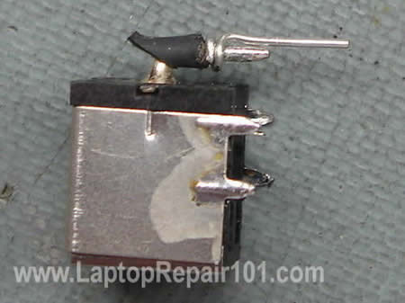
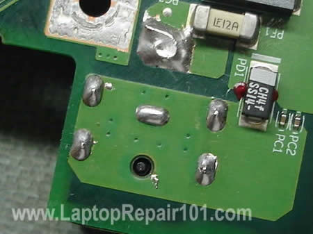
I pulled out the internal copper coating (I name it a sleeve) from the inside of the “+” terminal as it shown on the picture below.
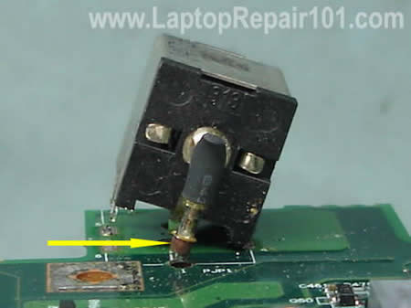
The the sleeve removed, it cannot be installed back. If you solder the DC jack back in place without this sleeve, it might work but the connection between the “+” lead and motherboard will not be reliable.
The following guide will help you to modify damaged DC jack terminal. This modification should work for most motherboards with soldered power jack.
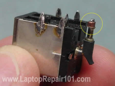
Remove the copper sleeve from the “+” terminal on the jack.
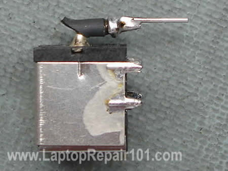
Find a small resistor or capacitor with thin leads. Cut off one of the leads. I’m going to use it to modify the motherboard terminal.
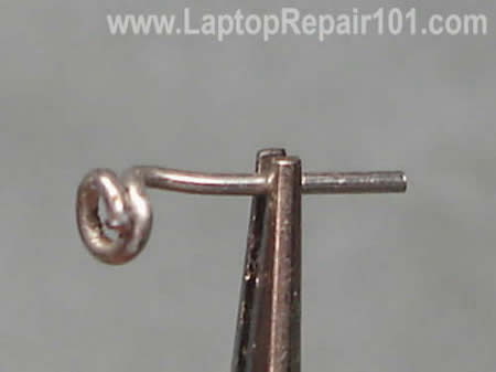
Shape the lead as it shown on the picture below.
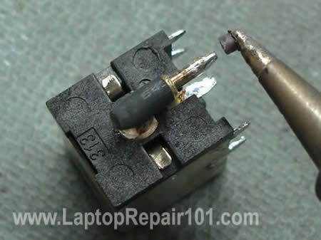
Put the lead on the “+” connector on the power jack.
Solder the lead to the power jack.
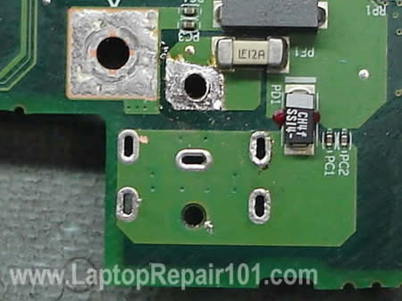
Now I’m going to modify the “+” terminal on the motherboard.

Carefully scrape off green varnish around the whole on the “+” terminal on the motherboard. You can use a small flathead screwdriver.
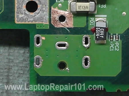
If the whole is not big enough for your modified DC jack, you can widen it with an awl.
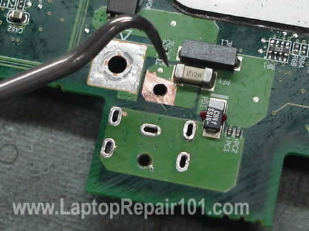
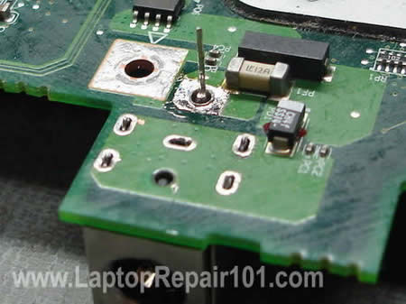
As you see, the hole on the terminal is now larger. Apply a fresh coat of solder on the clear area of the trace.
Install the power jack on the motherboard. Make sure there is no gap between the jack and motherboard.
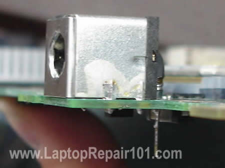
Here’s a view from the top side of the PCB.
Solder all pins except the modified “+” pin.
Now, when the power jack is secured, you can shape the lead as it shown on the picture below.
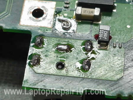
Solder the lead to the terminal. Remove excessive flux with an old tooth brush soaked in 99% alcohol.
Here’s a view from the bottom side of the motherboard.
Be very careful. Doing this modification you can damage the motherboard and make it unusable. Proceed on your own risk.
92 Responses
Donald
I have a toshiba Satellite A100 Model No PSAA9A-10U038
can anyone please tell me the part number for the motherboard ?
Or where i codl get a used mobo ? as the current one had a glas of wine spilt on it and its days are numbered 🙂
many thanks
Donald
Kevin
I must say this is a fabulous idea, i (PC tech ) actually tried the same method as you did here with a external lead to re-enforce the DC jack to the mobo but it only lasts a few days, even with my 2nd attempt
Because i think i missed the scrapping part from you lol, now i know the laptop i’m going to repair will last longer
Thanks so much
Willie Stovall
I’ve had this problem and read this repair tip and was wondering if you have tried it with a Dell. The center pin on the motherboard is the adapter sensor. I think the contact is between layers. I sure it will work with threw the hole.
Faraz
I bought my laptop a month back, and no it is not new, i bought it used so there is no warranty.
The problem is that it does not charge the battery. When I insert a fully charged battery it works fine, but when i insert the ac adapter it does not charge.
The local repair shops cant find the fault and they have returned it to me.
please suggest something……
Willie Stovall
Faraz, If this is a Dell, You may have a problem I’ve dealt with before. The center pin of the adapter is to tell the computer what adapter is being used. If it is the wrong adapter, the battery will not charge and/or not power the computer. Look on the bottom label plate. It will tell you the proper adapter to use.
Willie Stovall
I have searched the Internet over for a low cost way to reduce the possibility of overheating of a laptop from heat exchanger dust-bunny clog. I have found nothing. One morning it was my turn to make the coffee. There in my hand through half opened eyes I found the answer. The coffee filter. I held the filter to my mouth and breathed. Good air flow. I cut a square and typed it over the underside of my laptop where the CPU fan sucks up the dust off the desk. Works like a champ. There are thousands of laptop filters in the coffee filter bundle and masking tape is low cost also. I can see when the filter needs changing. Problem solved!
Didn’t know where else to post this.
Laptop Willie
check out laptopwillie.com
Stephen Weeks
I have an Advent 8111 and the power socket is faulty, I have tried my good power supply from my other Advent laptop and have the same problem, so I know it is with the socket within the laptop and not the power lead.
My question is this, how do I get to the power socket, I have taken the small cover off the bottom of the laptop and can see where the socket is but I need to remove the top of the laptop to get to the socket and I am not sure how to go about it. Can someone instruct me on how to do it.
Regards
Stephen
Kevin
TO Stephen Weeks,
If you can get the manual service for your laptop off the Mfrg. site,that’s big help.But if there’s nothing,then i’m afraid you need to tear you laptop down one piece by one till you reach the bottom of the motherboard alone.And i’m giving you a tip here: try to organize the parts you take out as much as you can ie: put it in the first place for the first piece\cover and correspond ing screws you have remove,the move on the second item+screws….and so on
JonTec
I recently tried to replace my DC power jack for my Gateway MX6446 laptop (about 2+ years old). After nearly a week of tinkering I found that I was unable to desolder the jack, even with a desoldering braid and vacuum pump, because it had solder on both sides. I physically dismantled the jack, leaving only the pins left on the board. In the process, however, I accidentally removed the entire positive pin including the sleeve. I was able to completely remove the other pins, clean the area, and solder together the solution explained in this article for a new jack. I removed the coating of the board to expose the metal and added fresh solder. I was then able to solder all of the connections on the board.
My problem occurred after reassembling the laptop. When attempting to connect the AC adapter to the jack (simply bringing it close to the jack) there was a quick spark and a visible arc of electricity after which I quickly remove the AC adapter. Is this an indication of a specific problem with my installation? I have included some items below which might be problematic.
-When removing the board coating, the metal and solder was very close (if the solder did not run over and connect with) to a random pre-soldered bead of solder on the board close to the positive pin.
-The positive pin solution protruded a significant distance beyond the original positive pin; could the power jump to other metallic components of the case?
-The power jack, similar to the one in this help page, had numbers on top. I ordered the jack based on its feet configuration, but the numbers did not match my original. Is this a serial number or a product number?
Thanks in advance. I can pass along a photo if necessary, but I am hoping that the arc is something distinctive.
Filiberto
Unfortunatly… You could have destroy you’re computer…
The Problem with these jacks is that sometimes they come in special configurations, so even if the are the same saze, and the terminals are in the same place, the Polarity may be inverse.
so you should have made sure the polarity match before putting the new Jack in place,
The fact that you had an electric arc means something shorted.
Also you should take care of not soldering oter componets or phats to ne part that you just scraped….
Kloghman
Hi.
first off all many compliments for the site.
I’ve found it ’cause I have a serius problem with an Aspire 9100.
I hope you will be so gentle to try to help me.
So …. My friends had a Power Jack problem, the electricity didn’t work
even if the “pin jack” of the DC adapter was inserted in the motherboard.
To bypass this problem she started to press the top of the “pin jack” in a really strong way. She was used to left three big and heavy books over the “pin jack” and in this way the battery started charging and the laptos worked also without battery.
But after some time she had to press more, so I decided to try to repair it.
I’ve opened the laptop and decided to take off the powerjack (it was broken the copper sleeve).
Then I scraped off a little quantity of the green varnish around the “+”,
and I solded a cable, bringing this out from the laptop.
Finally I solded two new jack, one to the DC Adapter and one to the cable solded to the motherboard. (I controlled the polarity with a Tester)
But I have a strange problem now!!!!
Even if the electricity passes to the motherboard (I have tested with an “Electricity Tester”) the laptop doesn’t start if the battery is not inserted.
If the battery is inserted, the laptop starts, but the battery doesn’t start charging.
It seems like if the electricity is not working, but as I said I tested it
I have uploaded some photos where you can see the electricity test results.
www flickr com/photos/33223425@N06/
I’m in your hands….
Please, help me or I will be killed by my friend !!!!!
PS:
sorry for my english!!
dlm
Hi, love your tutorial and i resoldered the power jack and it works. I did a real hack job tho. I couldnt get nice clean holes so i would heat one side and push an exacto knife blade thru and wiggle the best holes that i could. Even still I had to really heat and push the jack back into the holes and I dont think I got it as close to the MB as I would of liked. But it’s working god now, but I’m wondering if I’m on borrowed time.
Steve
This is a great tutorial. I’ve always told the customer the unit is dead when that copper sleeve comes out. Now I have a way to fix that for them. Thanks!
jo
i have a problam about compaq i connected tha ac pin my laptop light s r blinging what is is the falt
sherman
Can a laptop battery be charged any other way besides through the motherboard? Is there a way to charge the battery from a power source directly to the pins on the battery? (like a charger to car battery) If i could do this I could start my dead compaq R3000 and retrieve info to external hard drive. most likely solution to this could help many users. Thank you Sherman
sven
well im 15 from germany and i must thank you for this information….
NICE PAGE….
Tim
Thank you very much to this information. I just replaced the DC power jack on my Gateway MX6960. The jack and the board are a little different that what you show, but, most importantly, I did pull the cooper sleeve out with the bad jack. I would have never know about it. And, because I am not an electrician and have very, very basic soldering skills, I would still be trying to figure out how to fill the hole in the board.
Since I do not have resisters and such laying around, I used several strands of my cooper desoldering braid. I wrapped it around the positive post and soldered it in place prior to installing the jack on the board. Because of the solder, I did have to open up the hole a little. Though it took some time, and great patience, I was able to solder the cooper to the board in a similar fashion to the method you show.
Thanks again. The info was much appreciated!
colin
I think the suggested jack socket repair/ reinforcement is well executed. Before I disassemble my Toshiba SP6100 to see if my power supply interuption problem can be solved with this repair solution I would ask please — if there is presently nothing wrong with any of the laptops components before I disassemble and hopefully effect a supply fault repair after I reassemble the laptop can I assume that I will not have lossed its memory. ie will the windows xp still be there and all files etc? I am not sure if the athor of this site would answer please or any one else who would have a reply for me.
cj2600
Colin,
No, will not lose anything. All files are stored on the hard dive and if this repair is done correctly, the laptop will boot as before.
By the way, are you sure that there is a problem with the power jack?
If your Satellite Pro 6100 will not start at all and the power LED flashes orange light, resoldereing or replacing the power jack will not fix it. Most likely it’s poor connection between motherboard/video card/power board.
colin
Thank you very much indeed for your fast ,welcome and reassuring response c/2600. I will heed the extra tip aswell.
Old! you should see my Desktop PC !.
Peter Caines
EASIER WAY — PLEASE READ
There is a much easier way to repair the dc socket if the copper sleeve has come off –
All you need to do is order a small sheet of copper from ebay for a few pound.
then with the copper sheet cut a small piece 8mm / 4mm
then use you finger and thumb to roll it into a small tube that will fit on the dc pin where the copper sleeve came of
once on solder the copper tude to the dc socket at the end nearest to the plastic part of the dc plug so the copper tube does not slide on the pin
once secured use some pliers and gently press the copper sleeve around the dc pin.
once happy solder the dc power jack back on to the mother board.
Hope you understand the instructions as it got me out of a pickle.
Any comments or advice email me at pcaines_AT_yahoo.com
cj2600
Peter Caines,
Thank you for the instructions. Really good advice.
Bobinator
Could you do a quick post about what you’ve got in your soldering kit? Like just a picture of the stuff on a towel and a description of what each item is? I’m looking to get one and I can’t find any guide’s around about what to get/what to look for, etc.
I’m a laptop tech, most of this stuff I know but the soldering I never quite got the hang of.
cj2600
Bodinator,
I’ve done it already in this post: DC power jack repair guide. Do-it-yourself instructions.
junk_signup
First let me say this site has been wonderful. This is the 2nd DC Jack I have replaced. The first went perfect but this one did not. I followed the instructions on how to fortify damaged power jack connection in a laptop but ran into 1 issue that I think is causing my overall problem now.
After scraping the board, I tried and tried but could not get a fresh coat of solder on the board. How do you get solder to stick to the motherboard? It just wouldn’t adhere to the board.
So I thought if I put enough solder on “+” terminal extension it would seal properly. I finished and put the laptop back together. Now when I plug the power up to it, the adapter’s green light goes off and it beeps. Unplug from the computer and the adapter stops beeping and the light turns back green.
I’m assuming this Is a grounding issue.
So, my 2 questions are:
1 – How to you get solder to adhere to the motherboard?
2 – What is causing the adapter to act like this?
Again thank you
Dustin
I hate to ask such a simple question, but what’s the reasoning behind scraping off the green varnishing and applying a coat of solder in it’s place?
cj2600
Dustin,
To make a better contact between the power jack and motherboard. To make the connection stronger.
Lane Brubaker
This repair worked great, I did how ever pull out the sleeve and did not want to attempt the fortification so instead I scaped off a lttle bit of the board on both sides and cleaned the area up. Then after I soldered the other pins on, I kind of pushed the positive pin as close to the edge as possible and used a nice amount of solder. Has been working good so far. Also, Radioshack sells a nice de-soldering tool, it’s a combination soldering iron with a bulb type suction tool built in on top. This really saved me some time compared to the traditional type
Cincinnati Laptop Repair
This is probably the best tip on this site. I keep seeing mostly Gateways that have this problem, but I’ve also seen Toshiba’s with a ripped out connection.
David
This may be an out of left field question, but I have a new MB but windows is not working on it due to validation problems. So until I get it resolved I was wondering if I could use the board without any components on it to charge the battery. I mean can I plug in the ac adapter and then hook in the battery will it charge. I know this is a wierd question, but there is a lot of history behind this. Thank you for any help you can give.
cj2600
David,
You can do that. All you need is the motherboard, good working battery and good working AC adapter.
karamesh
I do not know how to post separatley. Mine is Dell Inspiro 6400.
If the AC power is cut, the laptop runs in the battery mode for
few seconds, the red LED blinks and it turns off instantly. By reading various forums I was under the impression that BIOS update might correct the problem and I update the BIOS version to A017. Now the BIOS has not detected the Battery. I cheked the battery several time and the all the LEDs in the battery are green. I do not know what the problem is. Now I cannot update or change the BIOS. And I am not sure that whether I have to go for new battery. Finally I found this excellent site, I’ll be thankful and welcome for all the advices.
Ka.Ramesh
cj2600
karamesh,
Could be just a bad battery. Do you know about Dell battery recall program? Check it out here. Dell Inspiron 6400 is mentioned in the list of affected models. Check the battery and maybe you can get a new one at now charge.
Mike West
I tried un-soldering the jack but I have no luck.. the solder is not comeing off, i dont care about the jack so i would cut it off if i could, any suggestions?
mp
@junk-signup / cj2600:
I have attempted to repair a gateway MX6453 laptop where the sleeve came out, but when I scraped off the green coating as described on this site, I too ended up with no copper to solder to… I think this is just a difference in the various motherboards? Checking the other side of the board (directly ‘under’ the body of the jack/positive pin) I did find metal…
John
I replaced the power jack on a gateway ml6232 and now after booting on a few seconds the fan stops goes through gatway screen then starts beeping telling me its overheating but why does the fan stop?
Great article loved it i did pull out the copper sleeve
Sangeeta
I have a question, my original power jack has 4 pins or say connector, while the new one I brought has only 3, I was wondering is it OK if I connect wires from only 2 (+ and -) from old power jack to new power jack outside the laptop? I will not remove the Old jack, but making the Bridge to new one and I have to plug the power cord to new jack which will be outside?
urasso
Hi Guys,
First off, I am indebted to to this site and the contributors that I finally got my Dell XPS Gen2 repaired. I want to pay forward and share my experience.
Yes, desoldering a Dell is HELL. I disassembled my laptop twice trying to desolder it. Finally, I went rambo on it by using a wire cutter, cutting across the jack and carefully tearing it piece by piece until I can see the holes. Do it at your own risk though, but I recommend it because I had no other way. Then, I use the solder iron to pierce the hole and removing the solder and cleaning it. The rest I follwed the well-written instruction here.
After reassembling it, the laptop would power on, but no screen, and then the laptop would power off in like 10 seconds. I also notice many of the people here are experiencing the same thing. Relax guys, all you need to do is to check and switch your RAM.
Hope that helps.
Thanks again to Laptoprepair101.
David
Thanks for the great tutorials on DC Jack repairs! I have an HP NX7300 and managed to pull off the tiny copper plate from the sensor pin’s through hole. So it’s not a sleeve, just one of those plates that surround all through holes. Any tips on fixing this or atleast what the technical term is for those plates? It must have happened to loads of people on all kinds of PCB’s.
cj2600
David,
I don’t know the right technical term for those plates.
Do you still have the copper plate on the other side of the motherboard? Maybe you can solder the jack to the remaining plate and then connect both sides with a short wire (jumper) if needed? I don’t know the layout of traces on your motherboard and cannot give you a better advice.
Brian Young
(Sorry for the cross-post, mods, but I’m hoping for fast feedback!)
This site has been so helpful, as I solder and re-solder my Toshiba A60/65. Long story short, the copper “plug” had a crack, so I used the guide to “fortifying” the damaged jack, and now I have a new issue:
When I plug in the power supply to test, it (the power supply, not the laptop) beeps repeatedly (short-circuit, most likely). I’ve checked the board for stray solder, and find nothing, so, here’s my favor:
Can someone with a similar lappy test continuity between the different parts of the DC jack? Even without disassembly, take the battery out, and let me know if you get continuity between the main pin and the pins that connect to the exterior of the plug.
When testing the jack itself, off the machine, I get no continuity between any of the pins (except the 4 that hold it to the board, which is the same piece of metal). When it’s on the board, or when testing the board itself, I get continuity between ALL the points (main pin, middle pin, and 4 outer pins). I can’t imagine that is correct — any suggestions/feedback? TIA!
Tom Evans
I recently bought a Dell Inspiron 5150 whose dc jack was completely ripped from the motherboard, I mean completely desoldered. Unfortunately, he copper sleeve which surrounds the adapter sensor pin, not the positive pin in this case, came off as well. I bought a new jack through eBay and resoldered it in place. Some trace metal surrounding the sensor hole remained on the top of the motherboard, but on the bottom there is no metal to solder the sensor pin to. Are you aware of any other location on the motherboard where I can solder a wire to complete the circuitry for the the sensor pin? Thanks for your help.
Steve
How much do laptop repair stores usually charge to resolder or replace the DC power jack? I’ve never disassembled a laptop before so I plan on taking my laptop to a computer/laptop repair store.
mat
hi
my nx 7300 has a problem …
everythings perfect in baterry mode
BUT
when i plug the power jack, it runs slower BUT A LOT !!
has anyone had this problem before ?
i took a look at the power jack and it seems to be ok …
cheers
debbie
Hi
My husband just had to repair my Dc jack on my acer 8930G the soldering was terrible, however we did not have any shrink wrap to put back on will this matter, the other problem is the length of cable they have left is so very very small it only just makes it to the connection, it was the black cable which had come adrift.
All seems to be working ok.
Thanks A Mil
paul wilmarth
can you use drill bit to remove old jack
cj2600
paul wilmarth,
I wouldn’t do that. You can damage the motherboard. Use soldering gun instead.
aslam
good morning sir
my probloms ihave a lap hp compaq nx 7300
formatt systome all install drivers last i nstall wrong bios
restart sysatom now dosnt working screen?
blank screen
plz
hlp me
frankie
hi,
this site is very usefull
i have a c640 with s faulty powerjack
i replaced it with an other one but still no power.
(he powers up with the docking and battery though)
is it a fuse issue? if yes , wich one?
thanx thanx thanx
cj2600
frankie,
I cannot tell if the problem is related to the fuse or not, but you should search for a fuse located somewhere close to the jack. Test it with a multimeter.
Paul
Hi I have a dv6500 with what looks like a blown fuse on the power connector/board. I went to connect the AC adapter after I got the motherboard out and heard some hissing sound and could smell burning rubber.
So I was wondering if there was a way to replace the tiny black fuse on the power board. It looks burnt and is moving somewhat. If nothing else works I can just order the power board which thankfully isn’t directly connected to the motherboard. But this part is very expensive and I would like to avoid replacing the whole power board if at all possible.
Paul
After researching some more I think the component might be a diode and not a fuse or resistor. I think it says D1 on it and the power board/usb combo part no. is 446524-001. I appreciate your help.
Paul
Hi again. I wish I could edit my first post and merge the three questions into one.
I have one more request. I have a touch pad cable connector/latch broken on my laptop. The touch pad doesn’t work as a result of this. I checked the cable itself and it looks intact with no breakages anywhere.
You have a guide for what to do if the keyboard cable connector is broken but nothing for a touch pad cable connector. Please help me out. Thanks.
klark
Hi, I need to buy a new adapter for my laptop. The input requirement is 100~220V, 1.7A. I found this adapter with input 100~220v, 1.64A, both output specs are the same. Is this adapter compatible giving the input Amp is lower? thanks.
khan
hi
i got problem with my laptop power board not main board.
how can find that
Philip
Hi. I just want to ask, i have an acer aspire 5920 laptop and my problem is i have a working charger for this but everytime i connect it the lights on the charger turn off so i have to unplug the charger to the laptop and unplug it to the electric plug and plug it again so the lights will turn on again then if i plug it to the laptop again it went off. What do you think the problem of my laptop? By the way thank you in advance if ever someone reply for my problem.
vince
hey my charging ports arc snapped so i soldered it and now it works but only if i apply pressure to it because the solder keeps breaking its a acer aspire 4720z and i wanted to kno if you knew how i could fix it for good or get a new one
Vivan
hi, i have acer aspire 2930 series and dead. i take out the battery and pluged in the power adapter. and I check the voltage on mother board which is solder part connecting to DC-in power jack, it shows 19v. Is it means that my DC-in power jack still ok?
I also check the battery connector, it shows 19v, is it means my mother board still ok?
I suspecting the power board is dead. but 2930 series have power board separated with DC-in power jack. power board only for power button and connected to MB, DC-in power jack also straight connected to MB. Not like other acer laptop which is DC-in power jack connected to power board and power board connected to MB, so if power board dead, there is no current goes to MB. I also susspecting the power board, because it looks burned(i can give the pic), but it looks doesn’t make sense because DC-in straight away go to MB.
Please help me, thanks.
Fillie
Hi,
I was trying to fix powerjack problem on toshiba satellite A75. I damaged on end of white ceramic component near the power jack with the solder. on the component its wirtten “F 12A”. (is is the same component which is visible in above pic no 6,7,8,&9) It has two metalic caps on its end. one matalic cap came off with when I was trying the solder I by mistake put on it. Is this component a fuse? How can I fix it?
Another tiny component named PC1 got a drop of solder on it. can that be fixed?
I will appreciate any help
Fillie
Ken
I have attempted to resolder a dc jack on my laptop. All soldering points look even, as the jack sits flat aginst the board and no spaces are identified in the soldering. However, when I connect the AC adapter the dc jack sparks. Is there something I can do to fix the sparking?
Thanks
elizabeth
hey i got a compaq laptop only had it for a year and when i plug in the charger it says its plugged in but wont charge and i got a new charger so what do i do to fix it i really dont want to buy another plzz help thanx
Techbox
All I can say is THANKS! This fortifying worked like a charm!!!
Enrique
Hola amigos. mi duda es la siguiente, tengo una portátil toshiba a205 y hace un tiempo atrás tiene el problema de que no prende si le conecto el cargador. solo prende con la batería ya cargada. Gracias espero su ayuda
cj2600
Enrique,
Can you test AC adapter with a voltmeter? Make sure the adapter outputs correct voltage. If not, try replacing the adapter.
Laptop Repair Rosemount
I have done this as well and your guide on how to repair a DC jack is spot on and I actually got some good tips just by reading this article, so thanks! Now I will be using alcohol to clean the system and that pump gun for desoldering. All great idea’s.
Robert
Just getting my feet wet replacing the DC power jack and bought a couple old toshibas A35s to practice with.
On your pictures you show the DC power jack with 6 points that are soldered. I understand the positive terminal and the copper bushing. I am assuming the center metal post is the negative and wonder does this also needs a copper contact point?
On the 2 outside tabs on each side, are these strictly for securing the tabs to the motherboard or do they serve a purpose?
I noticed playing and learning how to solder the DC power jack, when removing a jack there are also copper inserts that have come out.. is there purpose for tese or just for the DC power jack to have something to solder to for hold down?
I like your site and it is the best information site I have found on the internet.
scab
For those of you looking for help, the article plainly says that if you don’t feel comfortable working with solder you should not try this. Motherboards have more than just the two layers you see. there can be as many as 6 layers sandwiched into the board. This repair trick will only work if the plated through hole(that is what they are called) you pulled out isn’t internally connected to another layer of the board, and there is no easy way to check that without an x-ray. The cause of pull out is too much heat for too long. Also, look into a solder sucker with an antistatic tip and a metal plunger that wont break after a few thousand uses.
If you break a component on the board, you need to replace it. Learn how to use a Volt-Ohm Meter to test components.
Tony
Hi I have hp dv6-1053cl power jack need to be replace, i remove jack from cable and solder new jack in but still not work,can you give me diagram for it.thank.
cj2600
Tony,
Why did you solder a new jack? I believe in a HP Pavilion dv6 notebook the DC is attached to a power cable. If the jack fails, you just unplug the entire power cable with just and replace it with a new cable. If you do that, you don’t have to solder anything and there will be no mistake.
A new HP Pavilion dv6 cable is not expensive.
Ram PV
This website has been very informative.
I have my 5 months old Gateway NV59 laptop which fell down landing on the power port with adapter in. It was charging for about a month after that in a certain angle only and finally stopped doing so a week back. When I looked at it the pin that is supposed to be in the middle of the port is floating inside, clearly broken.
I have read the procedure but with the soldering/unsoldering on multi-layered mother board I am not going to attempt it myself. What are my choices — who will be able to repair these at the board level, rather than replace the entire mother board which ofcourse will be very expensive.
Thanks so much for the information and any help in advance,
regards,
~ Ram
shahat
hi sir
i have toshiba laptop satellite A40-231
DVD drive not working i can’t see any CD .It’s not softwer
i’m very far from any repair shops
cj2600
shahat,
Does it still play DVDs?
If the drive can play DVDs but not CDs, you have a failing drive. In this case the drive has to be replaced.
It’s not difficult to replace the drive in a Toshiba Satellite A40/A45 laptop.
Simply remove two screws on the bottom and pull the drive from the laptop. You can find a new replacement drive on eBay.
cj2600
Ram PV,
The chances are very good.
It’s not difficult to replace the damaged DC jack in a Gateway NV59 laptop, if you know how to solder of course.
If you don’t know how to solder, any laptop repair shop should be able to help you.
It’s not some crazy multy-layer motherboard.
Jodhbir
Hi,
I have Acer 5000 series laptop which had a broken DC power jack a moth ago. I myself replaced it with a new one. However, now the new DC power jack has a weird problem(It worked fine for one month).
Problem: At the positive terminal of the DC power jacked, soldered in the motherboard, shows 2.4 Volts instead of 19.3 Volts. However,when I measure the voltage without motherboard (take it out), it gives me 19.3 Volts, but when I solder the DC jack again to the motherboard, the voltage drops and it shows 2.4 volts.
The copper sleeve is there,and motherboard circuit looks good.I don’t know what is causing the voltage drop.
cj2600
Jodhbir,
You said the jack worked fine for a month and I assume you soldered it properly. This time it could be motherboard failure.
MEDI BARAL
my laptop is an ibm, but the problem is, it was damaged and didnt work (no power). I was thinking maybe the damage was caused by the lightning that struck nearby when my niece is using it with a globe tattoo plug it… simultaneous to the lightning i saw my laptop sparked… can it be repaired??? thank you…
cj2600
MEDI BARAL,
I cannot tell if the laptop can be fixed without seeing the damage.
By the way, today I received an IBM laptop for repair. No power, no lights, dead.
You know how I fixed it? Disconnected AC adapter, removed the battery and pushed on the power button for a few seconds. After that plugged the AC adapter back into the laptop and it turned on. Try this method.
sathesh
hello i have dell inspiron 1440 cannot switch on battery complete dead.(from adapter model-la65ns2-00)when charge the laptop connect to laptop light turn off.please help me !!
Jon
I have a Compaq Presario F700. When I plug the DC adapter into the laptop port the blue ring led on the port comes on solid and stays on. However, the laptop does absolutely nothing when I press the power button. I’ve attempted the hard reset methods and everything else I can think of. I know the jack on the mobo feels a bit loose when I wiggle the plug, could it be the jack even though I get the charger connected light still?
cj2600
Jon,
1. Possible memory failure. Try removing memory modules one by one. Test the laptop with each memory module separately, try different slots. One of the modules could be bad.
2. If replacing memory doesn’t help, this could be motherboard failure. Probably related to the graphics chip failure.
If you have nothing to lose, you can try this trick: http://www.laptoprepair101.com/laptop/2011/02/23/fix-laptop-motherboard-with-failed-nvidia-graphics-chip/
jasmin
My compaq presario CQ40 is currently out of warranty. And i found that when i plug in the batteries without AC, it cannot be turn on. Only when i plug in the AC then it can be turn on. But even when i turn on, i doesn’t appear BIOS and everything was blank. One of the thing i could notice is that, the both LED white light keep on blinking after the laptop was switched on. 1st LED light is located on top of “Num lk” key, and 2nd LED light located on the side of “Caps Lock” key.
can u help me figure out this problem.tq
Paul Sulwer
Jasmin, your battery is probably dead and unable to take a charge, so try a new one.
cj2600, thanks for the info in your article. I’ve salvaged the connections on a few damaged vias myself but they usually don’t come out looking as good or reliable as yours. The last laptop DC jack I worked on came out well, but you must admit that it’s easy to lift out the vias when the joint won’t heat up with a lower wattage iron, especially when you’re working with ground shields/planes which dissipate the heat too quickly.
ijat
Hi, i have emachine e525, the “+” terminal and ground show continuity, if i plug in power will this burn motherboard? how can i fix this. thx in advance !
Bjoern
Hello i have a Toshiba m30x laptop, the dc port was broken, i have make a bridge. no is the colore of display not black, the blsck is now red. Can you help me please? Thanks
cj2600
@ Bjoern,
Check the video cable connection on the motherboard. It’s possible the video cable not seated correctly. Try reseating the connection.
Randy
I replace dc jack on HP ZD7000 laptop . And now when i hit the power button all the top lights flicker it wont power up . It did power up before I worked on it, This is real what do think went wrong ,,only I did notice one pole didnt have a complete connection so i scrap the green away to see cooper and add more solder to bridge it but that did nothing to improve it the lights all flicker when i press power button. help
cj2600
@ Randy,
Maybe this problem is not related to the DC jack?
You said all lights flicker and it means the laptop is getting power through the jack.
I really cannot tell what is wrong without looking at the laptop.
Firefly
I was trying to repair the power jack on a Dell Latitude D520 laptop (works off battery; does not recognize power jack when plugged in). I was soldering to make the connection between the power jack box and the motherboard. I ended up using some excess solder, and I used a wick to try to get the excess off, but I may have made a connection I should not have. When I try to boot the computer, it powers up (from battery), enters the “DELL” startup page, startup bar finishes all the way across, lights flicker and shuts off. I want to try to remove the power jack connection, clean up any additional solder, then try to turn it on. My question is will the laptop power up if there is no power jack connection in place? Thank you.
Sean
Hey i have searched all over the weeb and cant find an answer….ur giudes r amazing by the way but none of them explain the need for the sleeve. I need to better understand what they r used for cause until this laptop repair i honestly never knew they were even there. I got this msi laptop after a user tried a self repair and the pin on the back of the jack runs into the board hole like yours above but it somehow looked different then i was used to seeing and ya its just shorted out so im pretty sure the previous owner fucked up the repair and failed to mention it but please let me know what the sleeve is ment to do that way i can better find a solution that resolves the board being shorted out. I appreciate everything done so far though! Mainly i need to know does the sleeve allow the traces in the hold to be connected or does it kinda shield them from being connected allowing the + pin to avoide contact with them and only attach to the top and bottom of the pcb and nothing in between?? Please let me know and thanks in advance for your time.
Al B
Toshiba Satellite A 65 – S 126. i replaced the DC – jack on this motherboard. all seem to go right, as removing the old one was clean, replace with new one an that also went in clean. reassemble laptop, plug in ac power. charging led on yellow after two hours it chance to green showing charge on batter. push power on then all led’s go out. let sit to see if it reset to charge. even try unplug and re-plug in. if i removed batter an the ac led come on put bat in an it green on bat. what you think? thank’s
Amol
it is useful, nice explanation
Thanks
ya
Awesome thanks!