This guide will explain how to repair a failed or loose DC power jack on a laptop computer yourself.
Disclaimer: I’ve made these instructions only for people experienced with soldering and repairing computers. If you don’t feel comfortable doing this job, please do not open the laptop or you can permanently damage your computer. Take your laptop to a professional repair shop instead.
Use this repair guide at your own risk. 🙂
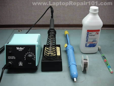
For this repair you’ll need the following tools.
1. Soldering iron or soldering station. I use Weller WES51 soldering station and for this job I set temperature to about 800-850°F.
2. I use high-tech rosin core silver-bearing solder from Radioshack with diameter 0.022″ ( Catalog #: 64-013 ). I think standard rosin core solder will work just fine.
3. Desoldering pump for removing solder around component leads. I use Edsyn Soldapullt pump, model DS 017.
4. 99% isopropyl alcohol and tooth brush for cleaning the motherboard from flux.
5. A new DC power jack.
Laptop DC power jack repair guide.
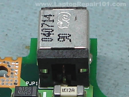
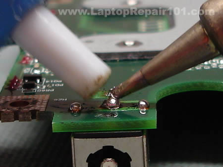
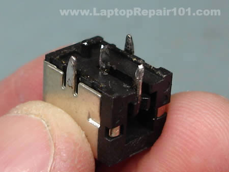
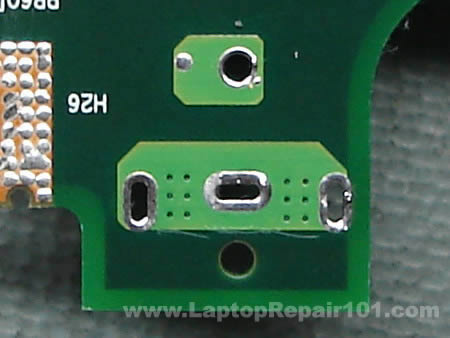
As you see on the following picture, the solder drop on the positive terminal looks different than on other three contacts. That’s where the problem is. The positive pin is not making a good contact with the motherboard and because of that power to the laptop cuts off when I move the power plug inside the power jack.
I’m going to desolder the power jack from the motherboard, clean contacts on both power jack and motherboard and then solder it back in place – this is the proper way fixing the power problem.
Start desoldering process with adding some new fresh solder to all three contacts. This will make old solder more flowable, easier to remove.
While heating one of the contacts, remove the solder from this contact using the desoldering pump. Repeat the same steps with all power jack contacts until you remove as much solder as possible.
Grab the power jack and carefully try removing it from the motherboard. Most likely you will not be able to remove the power jack the first time because there will be some solder bridges left between the contacts and traces on the motherboard. Carefully wiggle the power jack without applying any significant force and at the same time heat up all contacts one by one. This will help you to remove the power jack.
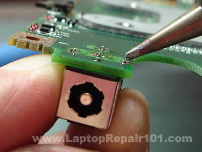
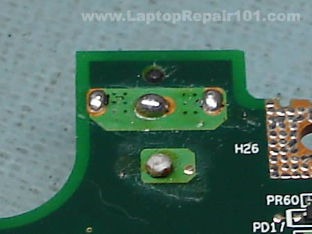
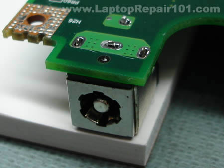
The DC power jack is almost removed from the motherboard.
Be careful. Inside the positive hole there is a copper sleeve which connects the terminal on one side of the motherboard with the traces on the other side. If you are removing the power jack with force, you can pull the sleeve from the hole. You don’t want to do that.
UPDATE: If you accidentally removed the internal sleeve, check out this post: How to fortify damaged power jack connection.
So, do not apply any force and make sure the solder is melted when you are removing the power jack. I hope you understand what I’m talking about.
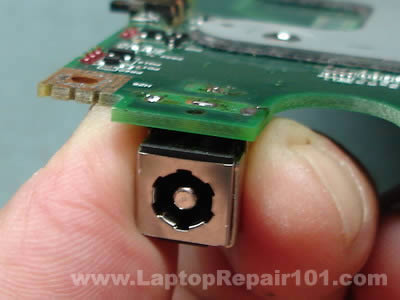
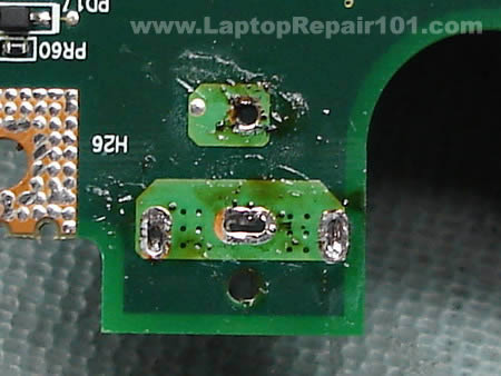
After the power jack is removed, clean all oxidized contacts with a knife.
Apply a fresh coat of solder to all contacts on the power jack.
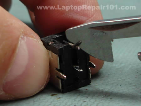
The power jack terminals will look dirty because of melted flux.
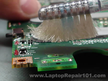
You can remove the flux using the tooth brush and alcohol. It’s not necessary but it will make your job looking clean.
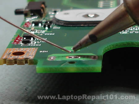
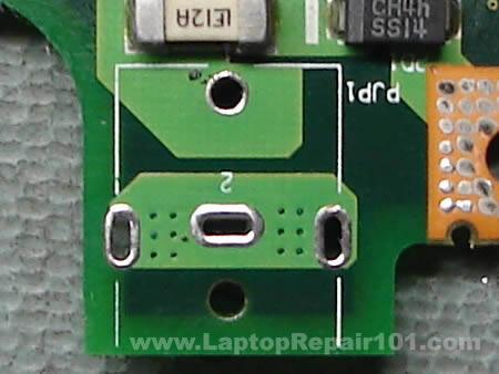
Apply a fresh coat of solder to all power jack terminals on both sides of the motherboard.
This side has been coated.
And this side has been coated too.
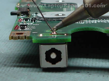
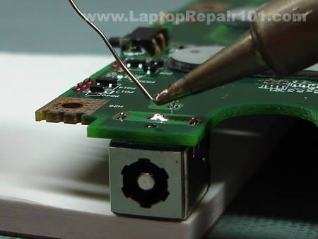
Now you can install the power jack back on the motherboard. Put something under power jack so there is no gap between the jack and the motherboard. Now you are ready to solder the jack back in place.
Solder all power jack pins.
The job is done and the laptop DC power jack is fixed. B-E-A-utiful!
Now just install the motherboard back into the laptop and you are done.

530 Responses
jbmurray
The dc jack area has broken 3 times (compac presario 2500). It is a fragile corner. Is there any ‘external physical support’ apparatus, that could suppot the area on the outside of the laptop, so that the area does not get so much pull/pressure on it?
David Chenault
Thank you for putting this on the internet in such a well organized easy to follow format. You are the Greatest man alive.
William Milkie
What an incredible site!
My son’s laptop has not worked for about a year.
While looking at it, and wiggling the power connector, I noticed the front lights flickering. Bad solder joint on the motherboard.
Using your directions, Toshiba A75-s226: I was able to take it apart, reflow the solder: made it slightly beefier, and repair it!
Good as new,
Thanks very much.
William Milkie
Jeff Finnan
I replaced the jack on a Dell Inspiron 1150. The battery is not charging. If I start up the 1150 with the AC adapter plugged in, I get a message that the AC power adapter cannot be determined and gives me some setup options. If the adapter is not plugged in, the 1150 starts up okay. However, my battery is just about dead.
Any suggestions?
Thanks,
Jeff
cj2600
Jeff Finnan,
Did you check the AC adapter? Maybe the adapter is dead?
Jeff Finnan
The charger is relatively new; however, there were some problems with the cord for it. I have ordered a new cord for it and will wait until it arrives.
I will report back.
Thanks,
Jeff
BlackTea
You are exactly right-on. My old laptop has exactly this loose power connection problem. You’re da Man!
Jeff Finnan
I discovered that I had an extra tip for the adapter, IGO 130. When I connected the one I had on the adapter, it would shut off. With the new tip, the battery started charging. Something must have happened to the tip, with the jack started loosening. It is my daughter’s laptop, she was pushing the tip around to get some intermittent charging until it would go no more. Now with new jack and tip, all appears well.
Thanks,
Jeff
Rob Nemlander
I have this power problem with my Toshiba Satellite P20 & will try to permanently repair my problem. My short term fix was to heat the power pin from the jack to the motherboard to repair the solder connection.
Now that I know how to take the laptop apart, I am going to attempt to replace the power pin with a piece of flexible wire so that the problem does not happen again.
I think the original cause was the flexing of the power pin & breaking away from the mother board when the power cord is flexing during usage.
Terry
Will any alcohol work or do I need 99% isopropyl alcohol?
Rob Miles
to Jeff Finnan about the Dell:
Some of Dell’s laptops look for a proprietary signal from the power supply sent through a 3rd pin. If they don’t see this signal, they will refuse to operate from AC power. This is to prevent you from using a 3rd party power supply, or one that isn’t matched to the current demands of that model notebook.
This 3rd wire is fragile and gets broken in the cable. This is most likely.
You could also have a problem at the jack which would be fixed by this guide. A 3rd possibility is that the PSU isn’t sending this signal anymore due to some internal failure – mine wouldn’t send when it was running off a battery back-up unit, for example, because it didn’t like the ‘dirty’ power input.
Contact Dell for a PSU swap.
Thomas
I had problems with my toshiba a75 s231. The battery would not charge and the power could not get to turn on my computer. Took it to a repair shop some 100 miles from my home and they told me that I would have to get a new mother board and other thing plus labor cost it would run around $650.00 to repair my computer. Then they told me that it would be better to just get a new computer instead of fixing it. I went back home thinking about buying a new one then I used my other computer to see if I could get help on the internet to fix it. After finding this sight I went to the store to buy me a soldering iron and took apart my computer for the first time. It wasn’t to hard and I got it fixed by my own hands and just paid $15.00 for the solder iron. Thanks for the step by step instructions I got my computer going and it feels realy good to know that their are people out there that can hep out and make a difference and save some major dollars. Mahalo nui loa, Thomas in Kona Hawaii
Donny
I ws wounder if you new y after i fix the dc jack the lights come on but thay go right off and the computer dose not come on
interphan
This is the most philanthropic site on the internet! I have been Googling for a site like this for hours for instructions to do it on my own and here it is! Thank you for your contributions to humanity and by undermining those swindlers who charge $280+ for this service. I am about to hit up Radio Shack to buy the supplies and do it on my own. I will update you on how it went! But one question that had been addressed before: is there an external physical apparatus that I can attach to the motherboard or jack that can provide extra support (i.e., to prevent this problem for ever occurring again?)
Thank you!
Wilson
Well I took apart my laptop and I need help with removing the power jack. I tried to desolder it using the iron and a desoldering band. The thing just won’t come out and the solder barely melts only at the exact point of contact. I’m using the generic $8 Radio Shack 15watt pencil solder. Any help is much appreciated.
Harlan
“Be careful. Inside the positive hole there is a sleeve witch connects the terminal on one side of the motherboard with the traces on the other side. If you are removing the power jack with force, you can pull the sleeve from the hole”
Is there a fix if you remove the sleve also?
cj2600
interhan,
I’m not sure if you can provide any extra support for the power jack soldered on the motherboard beside gluing it to the motherboard with epoxy, but it’s possible to relocate the power jack outside the laptop case. It doesn’t look sexy but it works. 🙂
Harlan
cj2600,
Thanks for the help and the link
manojtk
Great tutorial. I have had this problem on my toshiba m35x with battery not charging/DC jack loose contact for a long time and couple of days back it stopped charging completely, leading me to this site. I am a complete newbie wrt soldering and stuff, but I went ahead and bought all the equpiments suggested here for under 20 pounds, and it took me about six hours to dissemble the laptop again following the tutorial here, fix the soldering and put it back together. Needless to say it worked!!! Btw few variations between the instructions here and what I did
1. Didnt remove the modem card
2. Didnt remove the CPU
3. Didnt the remove the JACK completely – actually I tried but it was kind of stuck. So I just applied fresh solder on top of it.
Thanks again for putting together this tutorial. Great work!
wtf
im trying to do this and it is going well so far, but two screws on the base will NOT come out. my hands are bruised from applying so much vertical pressure to my screwdrivers. the screwdrivers are now all stripped. how the hell can i get these two things out?
John French
I’m about to start my third “repair effort” on my Toshiba. Couldn’t remove an F8 screw last time – had to drill into it with a small bit about the diameter of the screw threads – the screw head popped off and ran up the bit – later I was able to back the rest of the screw out of the base with needlenose pliers – I’ll replace the screw if I can get the Toshiba working. Other wise I’ll sell the whole mess cheap!
Brad
I have removed the power jack from the mother board successfully. I have a huge problem now……..The three holes are now filled with solder and I am having a hard time clearing them. I have tried using “wick” and I have also tried a solder pump, neither have been successful.
Does anyone have an idea as to how I can clear those holes so that I can reinsert a power jack? PLEASE help…….this site has been a life saver. Couln’t have gotten this far without it!!
cj2600
Brad,
Add some fresh solder into all three holes. Do not try installing the power jack at this time, just add some solder so the hole is filled up with the solder. Now melt the solder with the soldering gun and remove it with the pump.
Repeat the same process again: add solder – melt it – remove with the pump. Do it until the hole is clean. You have to repeat the same process a few times in a row for each hole. It’s very hard to clean the hole on the first try.
Usually I add/remove solder about 5-8 times until the hole gets clean.
Brad
cj2600,
Thanks for the quick reply! Can you please explain how adding more will clear out the holes? It seems as though each time I add, I am only picking up what I have added each time.
Do you think getting a smaller tip for my solder will hel with getting the excess that has filled the holes? Thanks……..looking forward to your help again.
MrBJ
I have the same problem. My holes are all blocked with Solder. I tried adding more Solder but didn’t work that well. Can somebody guide me and Brad in right direction…..Much appreciated.
Thomas
i tried using a toothpick and it got most of the solder away and made sure that the toothpick could go through the hole. you might have to wither the toothpick a little so it opens up the hole while heating it up. once the solder gets soft the toothpick should be able to poke through the hole
Steve
Does anyone have reviews of repair sites for the dc plug. I’m just going to send mine in to have it fixed.
Nur Hafiz
I’m having similar problems with my Compaq Presario M2000 notebook too. I had to wiggle the adapter to the power connector of the notebook or my laptop battery won’t charge and won’t turn on if it doesnt have it’s battery on. That metal thing which I plug into the DC gets extremely hot very quickly in matter of minutes also.
I’ve been looking for information on how to dismantle my notebook to get access to the DC power jack but looks like there’s too much risk involved. Too many screws to look out for and thin wires in the way. Almost made me feel like Im defusing a bomb or something. Im a college student living on college budget and couldn’t afford to buy a new laptop and the warranty is already up. I bought the laptop only 2 years ago.
I would really really appreciate it if anybody could give me a guide on how to dismantle my laptop and get access to the DC power jack. I’s gonna cost me $120 if I were to send it to the shop to repair.
It’s hard to go to sleep without knowing what’s to come.
adam
I see a lot of guys in over their heads here.
Guys, like said in the article, don’t do this if you’re not familiar with soldering techniques.
Pick up your phone book and find a local computer shop (NOT a box store, but a shop that does real repairs). Ask them if they do DC jack replacements. If they say “huh?”, hang up and call the next guy, until someone knows exactly what you’re talking about. Plan to pay $75-175. It’s a 2-3 hour job on most models.
cj2600
Nur Hafiz,
Here you’ll find links to HP/Compaq maintenance manuals. Find your laptop and download the maintenance and service guide, you’ll find step-by-step disassembly instructions in there.
Toasty
I would like to say thank you for this guide. Before I found this I was about to give up completely.
you see, recently, the power pin connector bent backwards inside my laptop and I had to leave the ac adaptor plugged in all the time to prevent the module from bending back in from re connecting the adaptor. Even more recently, the adaptor was knocked loose on the corner of the desk and the power pin broke completely. since I have had no experience replacing parts in the past, I tried looking for replacement motherboards, or alternate ways to power the laptop, but that didnt work out well.
The laptop, by the way, is an HP Pavilion ze4240
now I just need to collect the rest of the materials and a new power jack and I’ll be set. thanks again
Harry Stanley
Greetings from Scottsbluff, Nebraska …. Thank you for this wonderful advice and instruction. Harry
supa
thanks for this write up. I sought out a repair shop, but the ones that I called said they would not do it and referred me back to dell. they were lookin to charge around $200 bucks for the repair. I only bought the machine for $350 so it didnt seem worth it. This guide provided the extra look that I needed to do the repairs. thanks
Nick
Thank you for the tutorial. My gf’s HP notebook wasn’t working anymore and the little power symbol would only briefly flash when you stuck the jack in. I researched and assumed it was the same common problem and came across this site.
Taking apart the notebook was a bit of a hassle though I got it all apart, bought a solder iron and solder and a magnifying glass and seen that the back pin wasn’t making a good connection with the motherboard. I tried to solder it and then solder sucker it off, but that was futile. Also since I have never soldered before it was a little harder then I thought though I suppose a smaller tip would have made it easier. So I just put fresh solder all around the connectors, used some epoxy to hold the jack on a little better and put the notebook back together.
Everything is working great, and I saved $175 which the local shop quoted me. And best of all, my GF leaves my computer alone now!!!
PinoyEngineer
Tried this on my A70 and it worked! The disassembly guide is very accurate! Thanks and more power.
P Swinson
Hi,
I had the dreaded intermittent DC connection with an old Tosh Tecra 8100. Seemed a lot of hassle to strip it down completely so I very very carefully “dremeled” or milled a 1/4 inch rectangle of fthe bottom of the case where I reckoned the positive pin solder point to the PCB would be. Sure enough, exercising the connector had caused the usual, the soldered joint had failed. Remade joint thru the created hole. Then covered up hole with tape. I could glue something more substantial on but it is fine as it is. All working now for bout 10 minutes effort
cheers
Peter (UK)
Aamir
Thankyou so much …You made it so easy… I saved $$ ….really appreciate it… keep up the good work… now my laptop is up n running better then ever. Thanks Again.
sam
hi,
thnaks for this guide
but i’m having a serious problem after adding some solder to dc jack contacts . in facts i fixed power problem (battery charges normally but laptop in no longer booting
we could hear fans but nothing after black screen.
surely is not screen problem i noticed it’s ok when i increase brightness.
i’ve tried also by removing one of memories but nothing.
i’m sure that i’ve damaged Nothing in the mother…
could you nhelp me please.
ps: my pc is toshiba satellite p20 s103
DAVID
I’ve got a Toshiba Satellite A35 series laptop that needs a new USB port (one of the two ports broke). Do you have soldering and replacement instructions for this component? Thanks.
Ksideshh
Do you have to go through all 25 step of disassembly to perform the power plug replacement? Thanks in advance for your help.
K
the file clerk
o dear pitty thank you its actually functining now (although i may have killed my internet card in the process….) thanks though !
C Tobin
Just can’t thank you enough for the beautifully lain out guide. I actually received a Toshiba Sattelite as a “hey if you can fix it it’s yours” type deal. Lucky for me I found your guide first!
Thanks again,
C Tobin (USA)
Rob
When I plug my power adapter in, the light on the front of the laptop comes on for a second then shuts off. It will keep doing that if I pull it in then out. Is that most likely a bad connection with the power jack? or something else? Thanks a lot.
cj2600
Rob,
1. Can be bad power adapter. Test the laptop with another good adapter.
2. Can be loose power jack.
3. If not 1 & 2 then could be bad motherboard.
Bob
This is exactly what I have been looking for. The problem with the laptop I have is the middle pin broke out of the DC connector. I see there is a work around to remote the connector but do you know where I could get a replacement connector that I could solder to the motherboard?
Rob
I tried a brand new power adapter. I’m going to see if I can resolder the power jack now. I hope it’s not a bad motherboard, it’s probably not even worth buying a new motherboard with laptop prices going down so much. Thanks for your help.
Rob
I’m in the process of resoldering the power jack. Is there any way to test if it is powering the motherboard without putting the whole laptop back together first? I have a volt tester if that helps. Thanks.
Greg Ritsul
I am trying to resolder the power jack to the motherboard on a Vaio PCG-GX600 notebook. Only one little problem – I’ve removed every screw I could find on the exterior of the case, but still can not open the notebook to access the motherboard. What am I missing here??!! Toward the front of the notebook, it is reasonably loose (I could separate the top and bottom halves of the case without too much problem), but the back halves of the case are firmly sealed. Yet I can’t find anything else to unscrew to loosen that area.
cj2600
Bob,
It depends on the model of your laptop but most likely you can find it cheap on ebay.
cj2600
Rob,
Yes, all you need is three main parts: motherboard, CPU and memory. If the power button is located on a separate board, then you’ll have to connect this board too.
Assemble everything on your desk, connect an external monitor, plug in the power adapter and turn on the laptop. If everything is OK, it will start and you should get video on the monitor.
cj2600
Greg Ritsul,
I tried to google for PCG-GX600 and the only one site pops up, it’s my site with your comment. 🙂 Are you sure PCG-GX600 is correct model?
I posted links to some Sony Vaio manuals (including disassembly instructions) here. It’s possible that you can find model similar to your Sony.
JulieAnn
You are an absolutely fantastic human being! I’ll be using this over the weekend to try and repair my sad little Dell Inspiron 2200. Thank you thank you THANK YOU!
Bobby Reed
Nice tutorial, great pictures and instructions. Will bookmark, and use when needed!
bernie
Hi there, thanks for the advice. I took the lazy way, cleaned up all four solder points with a screw driver. Soldered all joints and bingo all working 100%, pity I bought a battery and adapter first. Great site.
jamie
nice gonna go buy a soldering iron now for £5 :D, hope it works well as nothing will oot on my computer ^^
Ron Buechler
Many thanks for the very clear and detailed instructions. Without them, I could not even have disassembled this overgrown calculator!
One question – is there any other source for the part other than ebay?
Best regards,
Ron
Randy
if this doesnt work, what else should i replace/repair to see if i can power up these two freebie laptops i have?
Toshiba Satellite A75-s206
cj2600
Randy,
Why did you replace the power jack in the first place? Did power LED flicker when if you wiggle the power plug or what?
Randy
yes, but nothing else.
I am going to find some new plug replacements and try again though, waiting for the mail man so to speak.
I got a slight orange blip of LCD light, then a red flashing one, then nothing.
Gary
Looking at this tutorial, it gave me an idea, i have soldered on at least 4 power jacks to my laptop(presario 2500), so i totallly dismalted it, took ou the old jack, and replaced it with wires heading directly to the power suppoly, because im not using this laptop for the batter functionality anymore, becuase 10 min doesnt get you far if u know what i mean, i just used a cheap 30 watt harbor freigh soldering iron, and the whole “repair” went smoothly. It took me a little over an hour to do it, but then again, this thing has been apart 7 times now.
Luke
Hi,
Great tutorial…definatly gave me some confidence boost :P. The laptop i want to repair is a really good one and i realise that if i don’t repair it, it will cost a bobm to get it proffesionally repaired, yed? So all im stuck on now is how to correctly dissassemble the case and also how to correctly SOLDER! Does anyone have a link to a useful website about these two problems (no offence). Ok thanks alot anyway,
Luke.
cj2600
Luke,
I posted links to some service manuals here. You may find your laptop in there.
You cannot learn it from books. Only if you practice.
Drew
Thanks for the pictures!! It helped out a lot.
Chris
Hi am in the process of doing this with my presario 2500. I was unable to cleanly get the power jack off so there are still pieces of metal in the holes in the motherboard. I was wondering if you had any suggestion as to getting this metal out? My new power jack is coming in the mail soon so if anyone has any suggestions.
Tom
Thanks for the pictrorial instructions they have helped me tremendously. I must say though, removing the old jack and cleaning the terminals is a lot more difficult for the unskilled than you make out, especially the positive post (or the one furthest from the edge) there is very little solder to anchor to. Nonetheless, I am thankful for your instructions.
I just hope I can put all the straps and screws in the right places. No doubt I’ll have one or two over.
jose
Hi,
I have an ASUS notebook with the following problem:
The notebook only works with battery power.
As soon as I turn ON the notebook, and the external power is connected, the notebook switch automatically over to battery power. It does not work anymore with external power. I cannot use the notebook with external power anymore.
The problem appeared when an other external power supply adapter (not from asus) was connected. The polarity os this power adapter was inverted, so something inside burned out.
Does anyone have an idea what could be damaged in the power circuit line?
Thanks a lot
cj2600
jose,
did you test the power adapter? Maybe this adapter is bad? You can test it with a voltmeter, make sure it outputs correct voltage.
Also, make sure your new adapter matches laptop requirements. The adapter must output the same voltage. Amperage on the adapter can be the same or higher.
Dave
I did this over the weekend, and the jack is coming loose again. I admit, I didn’t try to work solder onto each side of the holes, afraid of plugging them as others have mentioned. But, it’s already coming loose again. There doesn’t seem to be enough for the solder to grab onto to make a strong mechanical connection. I’m considering super glue for the mechanical hold, and soldering for the electrical connect. Anyone have better ideas or comments?
Dave
Follow-up. Cleaned up the board, burnished the contacts on the port, and drew solder down them so that it looked like they were twice as long as they were. I smeard the bottom of the port with 2-stage epoxy, put it in place, and clamped it in place with a spring clothespin. After it had cured an hour, I hit the solder on the contacts with my soldering iron, so that it melted down and formed a good contact. Using a toothpick, I worked a little more epoxy around the front edge, and not the whole thing is set up like a rock!
Sheri
Hi. How do you know when you have to replace the DC jack or not. The center pin which goes inside the jack is a little loose I can feel it a bit. Should it be replaced or is this normal? This is the second time I tried to fix this. I admit I did not take out the jack the first time but just took off the old solder and put new on. It worked for awhile but then got loose again. I didn’t see my power lite come on at all just the battery and the ‘on’ lite. Why is that? Should I be using some sort of glue as well. I noticed that there was some on it.
Josh
I have a compaq presario R3000 and have a power jack issue and it seems that it just becomes unsoldered everytime i repair it although i’ve never cleaned the surface after removing the jack. Coul that be why or is there another explanation for my problem? Please let me know some ways to PERMENETLY fix my problem.
cj2600
Josh,
That could be your problem.
In order to fix the power jack correctly, you’ll have to:
1. Remove the power jack and clean contacts on the jack. Apply some fresh solder on contacts.
2. Clean up contacts on the motherboard and apply some fresh solder on them too.
3. Solder the power jack back on the motherboard.
Brian
Hey guys, I too am having difficulties removing the DC jack from my Dell D600. The jack itself looks like ti has 4 prongs that are affixed to the motherboard via glue and 5 points that are soldered in.
Picture – http://images.marketworks.com/hi/72/72457/dellside2.jpg
My question is what is the best way to remove a jack that is glued and soldered in? I don’t want to apply too much pressure to damage the motherboard.
Brian
Nevermind i got it
mr. john king
hi, ref. DC Power jack.
when you move power cable, the power cuts out,
should the battery not kep pc running?
my laptop dont power up at all, but the blue power light on the front flahes 2 times,
so i am not sure if this is my problem
( HP Pavillion ze4800)
any other ideas?
George
Thanks for your steps. But I ran into a problem trying to coat the holes for the jack on both sides of the board. One of the holes got blocked with solder. How can I recover the hole? One of the pins of the jack need to go in there. Thanks
cj2600
George,
Apply some fresh solder on the hole, heat it up with the soldering gun and suck out the solder with the sucker.
John Richard
Hi, I have Toshiba Satellite M35X laptop. I replaced the dc power jack as described in your instructions. Everything worked fine. The power works now. The problem is I see nothing on the screen. It’s black. I put everything back the way I took it apart. Can you tell me what I did wrong and why I can not longer view anything on the screen. Thank you for this site and your help.
Warmest regards, John Richard
Joel
Fantastic walk through! I used this for my HP ZD7000. Ordered a 10$ DC plug from a guy on e-bay. Don’t get ripped off by going after the 25-30$ parts. Took my time working my way around the connectors desoldered the old one. Drank a beer to calm my nerves and continued on. Cleaned it up and put the new one on. Good as new. Only thing… I have about 50 screws left over. You think they really need this many fasteners to hold together a 8lb piece of plastic ;-)? Many thanks and again great walkthrough!
cj2600
John Richard,
Did you test the laptop with an external monitor? If you have no video on both internal and external screens, make sure the memory module is seated correctly.
If external monitor works fine but you have no video on the internal LCD, check the video cable connection on the motherboard, make sure the cable is properly connected to the motherboard.
brian
worked perfectly, thank you so much.
i originally thought this wouldnt fix the problem i had (having to hold the power cord in to charge the laptop) because on the outside the jack didnt seem to have any damage. im pretty used to soldering componants, usually much smaller than this, even though ive never worked on laptops before, so i figured the worst that could happen is i unnesessarily clean up a connection, so i went ahead and did it.
well it ended up being the problem, and this fixed it. once i opened up the laptop i found the jack itself had melted all over the place, and onto the contacts, so it was def in need of changing. the 4 prongs seemed to be making contact, but i guess the oxidation and melted crap was deterring them from being very good conductors.
John
hi, is there any way to remove the solder from the mother board without a pump, as i don’t have a pump. 3 2 of the four holes are blocked and i need to put the new DC power jack onto the motherboard? Any suggestions?
headborg
Hey, I found your “how to” instructions very useful several times- yes, I was a sucker for buying a toshiba a75. Now I have a related problem- the little black resister? next to the dc jack- labeled CH4h SS14 — it has poped/overloaded– I’ve called around and even taken it into Computek- Springfield– and no one seems to be able to
help me– surface soldier a new one in place– and I’d like to try it myself- but I need to find the component- would you know where I could find this part? And how difficult would it be to replace it? It appears to bridge over to the chassis ground?
cj2600
headborg,
Sorry, cannot help you with that one. All my soldering knowledge is limited to power jack replacement. 🙂
Bruce
Have compaq presario 1610. A tech who tried to fix it says dc adapter pulled away from traces and can’t be fixed. Maybe a dongle can be added further down the line as a work around. Anyway, need help finding dissassembly instructions. Tried your link but it takes me to a maintenence manual that is about cleaning, travel packing, but no dissasembly instructions. Thanks
cj2600
Bruce,
Not all HP manuals have laptop disassembly instructions, I believe only newer models have it.
brian
how do i check if the mother board is fried or if the jack is fried???
Chris
John,
Solder wick. Its copper colored, sometimes its called solder braid. Comes in a roll and is fairly cheap.
Headborg, check out Fry’s. Its an electronics store, to get a cross reference you might try a company called haystack.
Brian, you should be able to check continuity through the input jack that connects to the mobo.. Most voltmeters have this function available.
cj2600
Brian,
1. Test the power supply itself. Make sure the power supply is not dead and outputs correct voltage.
2. Take a closer look at the power jack. If solder joints have no cracks, the power jack is in a good shape but the laptop is completely dead, most likely it’s bad motherboard.
As Chris mentioned in the comment 98, you can check continuity with a voltmeter. If the motherboard receives correct voltage from the power supply, but there are no signs of life, apparently you have a bad board.
Andrew Smith
My A60 does not power p at all so i will try this method
as all that happens when i conect the power pack the pack starts to make this squeeking sound so im asumeing this is the problem I will post after i try this Thanx
kyak
i got a nec laptop the other day.it worked fine at my friends house,but when i took it home i think i messed it up,i forgot it was plugged in and i removed the battery while it was plugged in now it doesnt show any leds when i plug it up,do you think i fried the mother board or something,help me pls its a really nice lap top and i got it for free would love to fix it…
cj2600
kyak,
Try the following. Unplug the AC adapter, remove the battery, wait for 2-3 minutes. Install the battery and plug in the AC adapter. Try turning on the laptop.
Maybe the adapter is bad? You can test the adapter with a voltmeter.
SEMWANGA NICHOLAS
my laptop is just new and i hope to use the idea u have give mi.thanks.But do i need to replace a new jack for my laptop to work properly?the problem is that its jack port pin became loose.
David
I have a Dell Inspiron and had the original ac power supply burn out on it (no green light on the box, nothing on the voltometer) and found a third party adaptor that worked for charging. Then it stopped charging my battery and would not run the computer with the battery removed. No matter how much I wiggle it there are no flickering lights on the the ac indicator. I am in Taiwan where there are no Radio Shacks and only one Dell store (in a different town). I don’t have a soldering iron so it is in the repair shop and I have them looking at the power jack but I don’t hold out too much hope since I had no flickering lights. My question is there a way to make a standalone battery charger so that if my motherboard is fried (still runs the computer) that I can just charge the batteries seperate. Due to an error in shipping Dell sent me three batteries instead of one so I have plenty to charge and keep me in power. I would be interested in this even if I the the problem fixed.
Thank for the help and sorry for the long post
Desperate in Taiwan
Quophi
Anytime I turn my laptop (hp dv 1000) the battery led is on but the machince wiil not boot.Explain to me what i can do to serve my machine
cj2600
Quophi,
Could be memory related problem. Try reseating memory. Move memory modules from one slot to another. Test the laptop with another known good memory module if you have it.
Tony
i have the Toshiba A70 laptop and the AC adaptor is not charging my laptop. i know theres a problem with the DC not connected to the motherboard right. so i took apart my laptop and try to solder it myself. when i’m finishe i plugged the AC to my DC and get this burning noise coming from the DC then it started to smell like sometings burning.
Did i short circuit something? if so, is it possible to fix it or did i fry my motherboard? i can still turn on my computer fine just not with the AC adaptor plugged. should i buy a new jack?
Kish
I have a M35X-149S Toshibha laptop, currently ot does not start. Does this laptop have a problem with DC jack? Yesterday, while i was working monitor screen went blank, however, power light was on. I tried to turn it on and off to see if I could see any display but without success. After a while, even power switch stopped working. Now it is completely dead!!!
Does this laptop has motherboard problem or power (DC) jack problem?
Thanks for your help.
Krish
cj2600
Kish,
Can you see any LED lights on the front when you plug in the power adapter? If the power LED lights up but the laptop will not start when you press the power button, there could be a problem with the memory. Try reconnecting the memory, move the memory module into the empty slot.
If there are no LED lights, check the power adapter. It has to output 19VDC.
Kish
thanks for your advice. i tried what you suggested, but it did not work. the laptop is still dead. the power switch still does not turn on the computer, and there are still no lights and no response. i also checked the power adapter, and it did show 19VDC output. do i have to take apart the laptop and look for defects in some hardware (like the power jack, etc)? what are my options here?
thanks again
cj2600
Kish,
If the power adapter is fine then either there is a problem with the power jack or the motherboard is dead.
It’s necessary to take a closer look at the power jack. When the motherboard is removed, you can plug in the power adapter and test if power comes to the motherboard. It’s possible that you have a blown fuse witch is located close to the power jack. It’s possible that you can fix the laptop by replacing the fuse.
If the fuse is OK and motherboard receives power from the adapter but the laptop is still dead, most likely you have a problem with the motherboard.
Icydude21
I just want to say thank you soooooo much for posting this guide and helping us with this problem. I have fixed my laptop after it has been sitting in my closet for 2 years. I have tried multiple times for the past year to try and solder the power jack back on properly, but I was just not able to. Your guide, and the comments, and your responses all helped me to do it finally today and I am really really thankful and happy.
The main problem I was having was with actually soldering the power jack onto the motherboard. I still have not soldered it fully and properly, the solder is only sitting on half of the joint for each of the joints, but it is the best I could get it. The laptop is powered again, so hopefully the joints will last a long time.
Is it okay that the joints are only soldered on partially? Will this cause any kind of problem if I continue to use the laptop like this? Or is the only problem in doing this that the solder is more likely to come off again? Thanks again!!
cj2600
lcydude21,
I think you can use the laptop like that but I’m not sure if your soldering job will last forever. 🙂 Be careful when you plug and unplug the power adapter.
Gary
Is there any way to figure out where the screws go if you did not label them? It is an Acer Aspire 1640. The repair manual does not tell you this.
JT
Can you tell me where to find a replacement DC-In for an HP DV8013CL?
Jamie
This is an excellent guide, many thanks for taking the time to document your work.
JP
Thanks for the informative site…the pictures are great too. Here’s my problem: I installed a new jack in my HP Pavilion ZE4900. When I barely insert the power tip into the jack, just making the connection, I get power. When I completely insert it, I lose the power. I looked at the design of my jack from the rear, and when the tip is fully inserted, the (negative?) plate or “tongue” inside compresses down, which looks normal, but it looks like it disconnects from another contact above it. Is this because when running on battery power, that completes the battery’s circuit? If so, I suppose my solder of the negative plate is bad?
Lukh
Hi,
I just want to say: “THANKS ALOT”.
i have a Toshiba A70 Laptop and the power adapter needed to be replaced. I took it to the computer shop and the guy coded me $240.00. I could not afford it so I stop using that computer. but few days back i found this site and i fixed my computer, resolder the jack, and also clean it from inside. With the help of all the pictures I found that it was not that hard. so thanks alot guy. thanks alot.
regards,
Lukh
Faby
I need help!!!! My notebook laptop won’t charge. I was told that it was the DC adapter. I don’t know anyone who knows or does this. Do you??? If so, what do you charge???
Jason
In this guide, you used / repaired the DC power jack that was originally from the laptop. Correct?
I am buying a new DC power jack, so I do not have to “clean all oxidized contacts with a knife” or “apply a fresh coat of solder to all contacts on the power jack”.
Also, I do not have a de-soldering pump, is this tool necessary?
Ann
My power jack broke off so I replaced the jack and soldered it on firmly. Now the power only comes on if I hold the power adapter in firmly. Did I do something wrong?
cj2600
Jason,
No, it’s not necessary to clean contacts on the new jack, it’s ready to be soldered on the motherboard. You’ll have to clean contacts on the motherboard.
This tool will help you remove the old power jack.
cj2600
Ann,
Make sure the jack is soldered properly. I cannot tell you what is wrong without looking at the laptop.
Moa
I’m also a repairer like you. An hp dv9000 laptop powers up with dead screen and after 20 sec again reset. This loop happens for ever untill I power off the system. Screen is dead. Does it belong to graphic chipset? I tried external monitor, again no screen. Only reset and reset after 20 sec.
gerald
Help! I have a Presario 2500. Once I’m in Windows XP the power shuts off at random. When trying to re-install XP the power keeps shutting off during the install process. There are times, where, I’m in XP desktop and the laptop is on a firm table, the computer will run for hours (with A/C power plugged in). Then, if I sit on the sofa with the laptop on the cusion, it shuts off in XP only after a few minutes. I ran a temperature program which only showed a yeelow flag warning on the hard drive at 56 degrees celcius. Sometimes I have to wiggle the A/C cord to get the laptop to come on. But I’m not totally convinced that the A/C power connector is totally at fault. Is there software that will check the memory, and hard drive? Is there software that will let the computer run without a windows enviroment? thnk you.
cj2600
gerald,
Your laptop shuts down because of overheating. You must keep the laptop on a flat surface. Apparently, there are cooling fan air intakes on the bottom of your laptop and when you keep it on the cushion, the air intakes are closed. Without air circulation inside the heatsink your laptop overheats and shuts down.
cj2600
Moa,
Here’s what you can try in order to troubleshoot the laptop. Disconnect the LCD screen cable from the motherboard. Minimize the laptop as much as you can. Remove hard drive, DVD drive, wireless card, unplug the keyboard.
In order to start any laptop you need only three parts: motherboard (I assume the video card is integrated), memory and CPU.
If the laptop still doing the same thing, most likely you have a problem with the motherboard.
Stew
Laptop Toshiba A30 would not charge while running and the battery was going dead in about a 1/4 of the usual time. Lights flickered when plugging in the power jack. Took it apart and re-soldered. Worked well for 2 days. Turned it off and left on power supply over night. Next morning the laptop would not boot. Press the power button and all sounds good for 4 seconds then the fans stop and it does not boot and the power light stays on but the hard drive light never flickers during this process. Then realized the power supply had burnt out. It must have been trying to boot from the battery. I believe the positive pin of the power connector must have eventually shorted thus burning out the power supply. I have two of these laptops so I tested the cpu, hardrive, in the good laptop and they worked fine. Took apart the laptop and could see an indication of a short next to the positive pin of the power connector. I believe the pin shorted on the corner of the silver grounding of the female video connector located on the M-board. So I now have a couple of questions.
1. Is the positive pin supposed to make contact on both sides if the M-board or only one side? If yes do you solder both sides?
2. Are there several layers of tracing on one side of the circuit board or is there just one on each side.
3. What other steps to trouble shoot can I do?
Clearly the positive trace on both the cpu and other side of the positive trace connector for the power input is still shorting to the ground on the video connector even though I have removed the power connector. Things are looking a little messy even with the great care taken. I am considering to take a sharp exacto knife to go around the area of the video connector corner where I believe the positive pin traces are shorting, to sever the short. I don’t believe there are any traces there but not positive.
Any feedback or comments from the pros would be greatly appreciated. (Toshiba A30)
Thanks in advance for your comments and help!
Stew Lockhart
Alan
Hi
Followed your instructions for taking the Toshiba apart and fixing a new power socket everything has gone well until I have tried to re screw on the screen, the hinges seem not to want to turn so I can’t re screw in. Its a Toshiba Equium A60-181 and I was following the guide from the Sat A65 which as near as I could find.
Very frustrating not being able to complete rebuilding to check out my handwork Can you help please. Cant see why the hinges will not turn logic says they must!!!!
Regards
James Bayliss
Hello, thanks to your instructions I have managed to fix my wife’s ibm thinkpad 1200 which I dropped 2 years ago! Unfortunately during the soldering I broke off a component which looked like a resistor and it pinged across the room, never to be found. I think that it was part of the battery charging because the battery doesn’t charge now but it wasn’t any good anyway so it will be used like a dsktop.
Thanks again for posting all this useful stuff, I might have a go at the photo frame next with an ancient laptop of mine!
elizabeth white
Hi there, already done youre step by step instructions and the laptop still wont charge or even switch on. I really am stuck now! Please help!
cj2600
Stew,
Usually it makes contact with both sides. There is a sleeve inside the hole for the positive pin and this sleeve connects traces on both sides of the motherboard. You should solder the positive pin on one side of the motherboard but traces on both sides are connected by the sleeve inside the whole.
From my experience, Toshiba laptops has only one layer of tracing on each side of the motherboard.
Maybe you should try resoldering the power jack.
So the laptop actually gets power but will not start? That could be memory problem. Did you test memory in second working laptop?
cj2600
Alan,
Not sure what could be wrong. Are you trying to turn hinges with your fingers? It’s not easy!!!
First, install the screen back into the place. Second, rotate the screen so you can access screw holes. It’s way easier to rotate the hinges when the display assembly is installed and both hinges are secured in the laptop base.
cj2600
elizabeth white,
How can I help if I don’t even know what was wrong with your laptop and what you did?
don
I resoldered my jack as explained, but with a meter I read continuity between the center pin (I assume the +) and one of the other pins (the outermost pin). Is this normal or do I have a direct short? I obviously don’t want to fry anything! Thanks!
cj2600
Don,
Something is wrong. Apparently you bridged traces with solder. Take a closer at your soldering job. Do not turn on the laptop like that or you’ll fry the motherboard.
Karl
I need a way to source the generic connector name for the male dc power connector that plugs into a Dell Vostro 1400. I’m referring to only the actual plug on the power cord NOT the entire power cord itself.
THANK YOU very much for your assitstance
Vivienne
I have a question about the power jack, do they have a positive and negative points? I soldered a dc power jack on a sony laptop but there was no indicator for + or – side. Ive tried testing the power jack but I cannot tell if its right, I dont want to short or fry my laptop.
Bob
It can only go in one way, unless it’s wired
Vivienne
This particular DC jack can go in several different ways. If it only went in one way I would know.
Brad
Worked Perfectly! A nice $10 repair. Thanks for the great website!
marcelo
thanks… its really work… thanks a lot.. at least i repair my lap….
you are so explicit and clear…
best regards..
marcelo
Steelgod
Amazing.. it works ! Simple, direct and useful .
Thanks a lot man.
Sanjay
HI I have a HP Pavilion ZV5000 and the power jack has been repaired. The laptop worked for a while then it stopped working and the little light on the power cable transformer is lit before i connect it to the laptop but as soon as I connect it the little led goes out and the laptop does not fire up. What do you think may be causing this?
Many Thanks
Sanjay
cj2600
Sanjay,
It’s hard to answer this question without testing the laptop. Here’s my guess.
1. Possible poor soldering job. Maybe the power jack is broken.
2. Bad power adapter.
Anil
I have an acer with charging problem. I have tried resoldering the old power jack (having removed the old solder) but to no avail. I am planning to replace the jack but I have noticed that this jack has been stuck to the board with some sort of resin (glue?). I am wondering if it will be possible to remove the jack without damaging the board. Any suggestions for removing the resin (glue?) to get the jack out will be appreciated.
Rob Meyer
I replaced my dc jack and I tested the continuity and it beeps on my meter. But when I plug in the AC Adapter the led on the adapter goes out and get no power. I have to unplug the adapter to get the led back on. The AC Adapter is good because I charged my other laptop just fine. Why does the led go out and not charge my laptop.
Rob Meyer
I plug in my apapter and i seen a spark on the dc power jack is this a short and can it be fixed.
Jesse
Thank you very much for your tutorial. Although not an easy process, it was successful and saved me over a hundred bucks in repair costs! Keep up your good work!
Mike
Hey Cj..
Thanks for the illustration.. I have completed everything and reassembled. The laptop isnt recognizing the jack i installed or something. All pins are soldered nicely. However, I did not pay attention tto the “sleeve” on the positive pin. I did yank it out :/. Should have read on before pulling .. its a new jack from ebay as well. looks like the same one used in this article. any suggestions would be appreciated
Mike
Mike
resoldered the old jack back on and works like a charm..
let me clean out my heatsinks and fans too.. they were nasty
Thanks for the help!
if i followed the first instructions i wouldnt have needed to buy the new jack 😉
Mike
rod
what is the orange/amber color on the motherboard where you apply those solder coat? what happens if that orange/amber color got removed while desoldering?
ivan
have same problem , but dont have power jack on motherboard
pls email me and send you pics
Martin Sheldon
Rob Meyer it sounds like u have a short on the board, the boards are multilayered and have tracks inside the board. Did you notice any damage to the power jack area, was any of the power jack contacts on the board black or crispy? if so then its likely that this is where the short is and its terminal, new board required. If not then its likely to be a faulty IC or something on the board, if nothing is obviously damaged on the board like a burnt/crispy chip then its probably a faulty IC shorting. This guide is good, I’ve been doing jack repairs for a few years, the only thing I would suggest is never use the old jack, if the centre pin is loose then its likely to be damaged and will more than likely work loose again, always use a new jack, they only cost a few quid from ebay!
Robin
Thank you for your help on the DC power jack as well as taking the whole thing apart , that was not easy. Now I’m afraid putting it back together is going to be a bigger nightmare for me , I would appreciate any and all information that would benifit the reserection of this master piece.
Ron
Good advice! Everyone should read the part about the sleeves through the Mb,Very Importaint not to Damage the board.
Rob Meyer – Sounds like you have a bad Mb. Thats a short condition on the DCV.
I have the same Jack problem as so many do, Glad I found this. The service Manual is on Dell and works through your web browser. Thanks for the Detailed Steps. Going to have fun fixing the laptop.
Nathan
Hi, I was just wondering if you might be able to add a little thing about how to match the DC power jack to the barrel of your AC adapter in the case that you need to replace the DC jack.
The weird branded Enpower Laptop that I had to replace the power jack for doesn’t have a part number I’ll see if I can’t find it though. Just need to find a workable DC Jack that’l work with a LSE0202A2090 AC Adapter. 20V, 4.5A 90W Max. Looks like a 5.5mm barrel. I could be wrong though.
livi
Hey i’m pretty sure mine has broken, i asked at the shop about it and they said it would cost £200 to repair -___- now that isnt far from what i paid from my lappy haha! is that amount accurate? because ur guide made it look not too hard (not that i would ever atempt it myself)
Jim
I can’t seem to get the last bit of old solder out in order to push the pins on the power connector through the motherboard. I am using a vacuum desoldering bulb. Any other ideas?
Thanks
Jeff
I have a Toshiba A65-S126 and Iafter desoldering the five contacts of the DC jack using a pump and wick, I still cannot remove the Jack from the Board. What am I doing wrong? anyone have any good suggestions? this is a five pin DC jack and know matter what I try it just will not come off.
T Moore
I followed all these instructions and my A70 is now working again and no longer destined for the scrap heap.The only thing that you should do in addition to these great instructions is note where each screw goes as some are different lengths and I put the wrong one in one area and my DVD player would not go back in place as it protruded through the motherboard.I am no electronic wiz but will have a go at most things and for $40 australian for a new DC jack I am all up and running again and it was no too difficult.
Jim
Toshiba, M35X
Thanks, I found your instructions easy to follow and I found that the problem was a little more then resoldering the jack. I have ordered a new jack and will install it when it arrives
JKay
Thanks a lot for these instructions!
For $4.50, I saved my Dell Inspiron 6000.
A couple of things for those who might find themselves in the same spot, on the same laptop:
1) I could _not_ get the darn thing off. I finally snipped it in half, longwise from where the ac adapter plugs in, with a pair of wire snips. 🙂 Not for the faint of heart….. I imagine the right thing to do would be to be patient and not do something crazy.
BUT…I did it, and it made it much easier to pull it out, one-half at a time. Just use a pair of needlenose on the half-piece, apply heat and voila.
On my first attempt I reassembled the laptop only to find the same “ac adapter not recognized” message. I disassembled all the way down, heated up the iron, and took a second look at the middle pin, furthest from the adapter opening, the one that carries the voltage back (19v?) and tells the laptop that you have a genuine Dell adapter. Sure enough, I hadn;t gotten a good solderpoint. Heat, more solder, reassemble and sweetness.
Thanks again for the great instruction!
CRN
Thanks to this article, I saved my HP ZD7000 from the scrap heap! Fixing it with a replacement part bought from Electronomax on ebay, I was able to replace the DC jack with little effort. Unfortunately, I should’ve documented my screw removal a little more carefully as I ended up with about 6 extras screws after reassembly, but everything else feels solid and I did it myself!
ric
after i resoldered power jack the led lights were flickering. what is that a sign of? loose connection?
charasoverride
you are a crack!
thanx for this wonderful tutorial!
nick
if you find that the scren still flickrs it may be the pin insde the power supply s loose… relace the unit on te motherboard alltogether that should do the trick
Whohlme
Hi,
is it possible that I use a small de-soldering bulb from radio shack, or should I get the elongated one that you use? Thank you.
cj2600
Whohlme,
I think so. As long as it works and you can remove the solder with this bulb. I haven’t tried it myself.
Whohlme
wow! that was a fast reply! Thank you. I read a general soldering site and it said bulbs are good for general purpose work but the pumps have more suction power and make things easier. I got the bulb for Christmas, but since they are roughly the same price, i may exchange one for the other.
Also, would a solder accessory kit be worth keeping? It has heat sync, brush, and probes. Thanks again
Louis
The solution to my problem on the very first page of the first site I visit. Must be a world first.
David
Hi,
How am I suppose to resolder the connection at the same time follow the assembly steps on this page?
R/
David
cj2600
David,
I guess you’ll have to have a second working computer or print the guide. 🙂
dezz
After following these instructons, my laptop now charges but my screen now won’t come on and the pc shuts down shortly after i turn it on. Any tips??
CB
Laptop repair guy do you have a degree in engineering or something cause the content on this site is excellent !!!
Geri
Replaced the AC Jack in my Dell Inspiron 5150 and when we plug it in the right and the left front green LED lights are flickering rapidly. The middle one does not come on. We checked the adapter and it’s sending 12 volts fine. Any suggestions?
Caz
Laptop dc in jack repaired many thanks, I can not get the keyboard strip back into place it is very difficult as it sits under the motherboard,
PACKARD BELL EASYNOTE
can you provide any suggestions.
thanks.
Yesenia
Can I use Silicone Grease instead of Thermal Grease to put on the CPU?
Jose
After following these instructons, my laptop now charges but my screen now won’t come on and the pc shuts down shortly after i turn it on. Any tips?? could it be my CPU?
Jeff
So my Dell Latitude D505 showed all the symptoms of a failed dc power jack; so I took it all apart down to the motherboard and then took the motherboard to a laptop repair shop to have the power jack resoldered. After putting it all back together the computer still has no power.
1. Is this b/c the battery is still completely dead?
2. Bad Motherboard?
Any suggestions from this point would be greatly appreciated.
Dave King
On the picture where you see the pads you want to do more than just desolder and stick the new jack in. The offical Toshiba fix is to do this and then run a bead of hot melt glue around the connector. Thats a little better but will eventually work loose.
The trick to fix it so you can forget it is to scrape the entire pad free of the green coating (solder mask). Then insert the new connector and tack it in place with a small bit of solder on each pin. You do this so you get the position right. When you have it in place solder the entire pad. It will take a bit of solder but when you have it soldered you should have a smooth solder layer with the tips of three pins sticking out. Normally you don’t use anywhere near this amount of solder but in this case we are using it to provide mechanical and electrical strength. Not exactly what solder is meant for. You can also do the hot melt glue but its not required.
The problem or one of them with the Toshiba connectors was someone was a bit too tight on the solder mask around these pins. So the result is there is not much solder and the transition is too sharp from pin to pad. Normal use will crack the solder sooner or later and you know the rest. Scrape the pad and you have a bullet proof fix well until you wear out the pin ;-]
otho
hey ya all, i have a dell c640 that wouldn’t power up nor charge battery while pluged … i tried my battery on a friends computer and charged just fine… connected the dc adapter and worked aswell… i assumed that i had to change the dc jack on my motherboard , so i did and i still ha the same problem… it’s so tiny it’s a serious bi**h
what do you think the blem is ?
Jimmus
Hey, I use an Alienware Aurora m7700, and this guide really helped me fix the power problem. I would have to swivel and move the cord just to get power.
However, after I put it back together, my laptop got power, but won’t turn on. It charges, but when I hit the power button, it blinks all of the lights, and then nothing. It goes right back to charging. Any ideas?
Meg
I have a Toshiba Sattelite L355D and it’s a great computer but the thing thta pisses me off about it is that the DC charger is sticking out so much when you plug it into your laptop. So, yeah as I was wakling by a door entrance on wireless, I had bumped the wall with it ever so softly and it got loose. I got so upset but luckily it was anything real serious. The guide is great but I don’t think I have those things to fix it lol. I’m only 16, I’d probably murder myself with that thing by mistake. But, it looks very handy. Nice work on the guide.
Amy
Thanks for these instructions. In your opinion, I have a Dell Inspiron Laptop. The customer works fine, I’m not getting any error messages when using it. About two weeks my daughter knocked it off the computer table on to the back edge (where the power cord plugs in). The next day I was using it and realize that my screen had dimmed and that the power cord wasn’t being used only my battery. I continued to use the laptop for an hour or so, so I could finish up my project. Again absolutely no problems at all, internet was fast, programs loaded, etc.
In your opinion do you think this process you have provided will correct the problem?
cj2600
Meg,
I don’t like how the power connector on this model is designed either, it’s very easy to break.
In a Toshiba Satellite L355D the power jack is NOT soldered to the motherboard, it’s attached to a power harness.
In your case you either broke the DC-IN jack or the mounting bracket on the base assembly where the DC-IN jack is mounted.
If it’s just the jack, it’s necessary to replace the DC-IN harness.
If it’s the mounting bracket on the base assembly, it’s necessary to replace the base assembly.
By the way, it’s likely that you broke both.
Kyle Igantowicz
GHETTO WAY THAT WORKS!!!!
The peg inside my computer broke, and I was about to try to replace it, but if you like do things kind of ghetto like me, I discovered an option. First take out the broken peg if it is still in the end of the power adapter, and in is place, fit in 4 pieces of 2 inch long copper wireing. Then cut them all at once, just so the copper is only slightly coming out of the end of the power adapter. Does not work perfect, and you need to wiggle sometimes, but better than getting rid of the computer, or trying to fix when you have no experience.
Dennis
I have my Dell Inspiron disassembled but there is no physical evidence that the power jack is bad, Can I plug the ac adapter into the motherboard and test voltage and continuity with the motherboard removed from the laptop without causing any damage to the motherhboard circuitry?
Thanks.
Misha Koshelev
So I’ve disassembled my inspiron 600m and soldered on a new power jack. Unfortunately the service manual did not go far enough as far as getting access to the motherboard, so I improvised, but in the process of moving parts (off my bed, ok so I thought it might not take as long as it did) I don’t think I _quite_ know which screws go where in the parts that I did after I finished following the service manual. Any help would be appreciated.
Thank you
Misha
cj2600
Dennis,
Yes you can. You will not damage the motherboard if you know what you are doing. Sometimes, when I’m not sure if the jack is bad or not, I test motherboards like that. I plug the AC adapter, connect my multimeter to the solder joints on the jack and start moving the plug inside the jack at the same time looking at the voltmeter. If power cuts off when I move the plug, apparently it’s either bad connection between the jack and motherboard, or the jack is bad (I assume the adapter is working properly).
cj2600
Misha Koshelev,
Are you looking at the right manual? The Service Manual for Inspiron 600m explains how to access and remove the motherboard.
Ryan
I never thought I could pull something like this off, but it worked!!! Thanks so much for the step-by-step!!
altair
hi i have a compaq laptop . few days back due to some power fluctuation i laptop stopped charging . when plug in to the power i am getting the burning smell. so when i have read u r post i opened the laptop to check the dc power jack . my dcpower jack is covered with some plastic sheet . sheet under the dc power jack is fine . but adjacent to it has got burnt(just near one of the pin of the jack ) . now i am unable to figure out if there is any part that has got burnt out or is this due to dc power jack problem .
cna you please help me to figure this one out
leidiana frerichs
Hi, i have a tx1000 hp pavilion that got the lcd speaker connector is broken. that connector is the one in the motherboard. where can i get that connector? I know how to replaced it. please let me know the company where i can get that connector. i don’t know the part number to do the search.
please
Christy McStinkles
Amazing tutorial!! I’m in the process of replacing power jack on HP zv5000. Do these jacks have any copper connector on the jack? De-soldering was a bit messy and I have a piece of copper left over from something ( maybe a different project). It doesn’t look like a the plug shown in the pic. Thanks.
cody
I have a Toshiba A75. I took out the mother board and am looking at the power jack. My question is, are the 3 solder points in the middle of the jack all negative and is it ok to have one pool of solder to flow over all three? I saw a photo were the power jack was left on the outside of the laptop and just the wires were run into it and soldered to the mother board. The negative wire was soldered across all 3 of the contact points in the middle of the jack. Is that OK?
RobertM
Hi, I’ve run into a Dell laptop that seems to use different solder to connect the jack’s external case to the motherboard. It is a nine pin jack (3 rear, 2 center underneath, 4 casing pins).
All but the 4 casing pins desoldered nice and easy. The 4 casing pins (which, btw, are soldered on top and bottom) have solder that would not even melt using the standard guns (35W and 45W) we use for most repair jobs. Fun job. The “big” gun managed to melt it.
Wish I remembered which model (sorry, work on many of them a month).
Anyway… very secure jack in that model – sadly the customer dropped it while the DC adapter was plugged in, which shattered the inside of the jack.
Rami
Hi,
I had the same problem on my toshiba,
I did exactly as you show above, excep that I also removed the LF12A next to power jack and by mistake soldered it back in in the opposite direction,
A. what is this unit at all?
B. Can you please send me a photo simliar to the 2nd photo you posted from top. under the LF12A theres a PC1 typed on the motherboard, should there be any thing it seems missing on my laptop.
Thanks.
maria
Hi, I have a Toshiba Satellite A75-S209. I have tried to replace the DC jack, and it was successful for about 5 minutes. I attempted to boot up my computer and the repair turned out to be no good.
So the laptop was taken apart again. We have placed a meter on the DC jack and there is power getting through.
But we have placed the same meter on the small white rectangle with the funny L1 with a F in the middle and a 2A after (pictured in the second picture) does not have an amperage on the end towards the center.
I believe that is the part that needs replacing, but I don’t know what that is. Can someone please help me by identifying that part?
Thanks so much
Maria
Lisa
Hi all.. hey I have been working on this compaq m2000 for about 2 weeks now. I ordered a new adapter. I would like to know if anyone knows where I can just buy the whole dang peice. On this serie’s its on a separate power board from the mother board. I found 1 on ebay.. just one. I have searched all over for this thing. Its all attached and ready to place no sodering or anything. I have tryed to sodering and that didnt work, now I have the new peice and cannot get the one I sodered off lol.. ooooh my. The laptop was working just fine and this is the only prob… does anyone know where I can buy the jack board with the jack or without it I guess.
Thanks
Fran Rohm
I have a sony vgn-690, the dc adapter was broken I replaced the part, it had no soldering involved. It worked great for two weeks know the computer will not start once again. Is there anything I can do to chek the mother board. I just don’t understand why it would work great then stop working .
Cathy
I have a Dell Latitude D600. It can run on a 65W PA-12 (model HP-OQ065B83) or PA-10 (model PA-1900-02D, don’t know wattage) family of Dell adapters. Both models have input of 100-240v 50-60hz, output of 19.5v. PA-12 outputs 3.34A. PA-10 outputs 4.62A.
I normally hook the laptop to the PA-12 adapter. About 2-3 weeks ago, I noticed that the icon which shows if I am on battery, AC, or AC and charging, kept flickering between AC and battery power. Finally, it stopped charging the battery in addition to not powering the laptop. I figured it was a problem with the AC adapter. Luckily, I have another PA-12 at home. So, I started using it. Everything worked for a while. Then, the 2nd PA-12 adapter started to act the same way as the first one. I have a docking station which is hooked up to a PA-10 adapter. So, I took the PA-10 and used that to run my laptop. Again this worked for a while and then the same problem. So far, 2 PA-12s and 1 PA-10 had stopped working. Then, I took the docking station (luckily it is small), connected the PA-10 to it, and docked the laptop. Everything worked. But soon after, I started getting a message that the laptop is docked, but the AC Adapter type is not recognized, and to undock the laptop or use another adapter for the docking station. I took the PA-10 and hooked it back to the laptop and removed the battery. If I play/move the adapter’s plug on the laptop, sometimes the PA-10 will work. However, I get the message that the AC Adapter type is not recognized and the laptop will not run optimally. I have a choice to press F1 to continue or F2 to setup, etc. I press F1 and the laptop will boot. (This only works on the PA-10. It does not work on the 2 PA-12.) Unfortunately, the laptop will be working and suddenly decides it does not have power and turns off. All along, I thought I have a defective jack (since moving the adapter wire sometimes works). However, I have another PA-12 at work. So, I plugged my laptop to that adapter (my 3rd PA-12), and everything works. It charges the battery and runs the laptop without the battery.
My question, is something on the laptop causing the AC adapters to fail? So far, I have 3 adapters that are not working. I fear my 4th adapter will go the same way. Is this a bad jack issue (I bought replacements jacks just in case). Also, why did the laptop suddenly stop recognizing the adapters? Is there anyway I can fix the 3 adapters? (I’ve checked all 3 adapters with a voltmeter, they all put out the correct near 19.5 v). I’ve also gotten to the point where I have the motherboard out of the laptop, but, there is a steel casing around the jack and motherboard. How do I remove it?
cj2600
RobertM,
I agree. It takes more time to remove the nine pin power jack from a Dell laptop, it’s very solid.
I can remove most power jacks from Toshiba motherboards in 2-3 minutes, but when I work with Dells it takes some time and effort.
cj2600
Rami,
It’s a power fuse. I believe it doesn’t matter how you solder the fuse, it could be solder both directions.
cj2600
Lisa,
I think you are talking about the power connector board. The HP part number for this board is: 382414-001
Google the part number and you’ll find it.
If you look at Google images, you’ll see the board. Is it the right one?
cj2600
Cathy,
Do you have another Dell laptop at work? Can you test that laptop with your adapters?
I think there could be a problem with your motherboard but I’m not sure what’s going on. I guess you’ll have to take a closer look at the power jack and see if it makes bad connection with the motherboard.
In order to remove the motherboard you can follow these instructions.
Cathy
cj2600:
Unfortunately, I am the only one with a Dell (I work in a 3 people office where I use my personal laptop for work stuff), so, no one can help me test the adapters.
I have followed the instructions to remove the motherboard. But, the motherboard still have a steel casing on top even when I pull it out of the laptop shell.
Cathy
I found someone with the same laptop and tried all 3 adapters. They worked. I guess it is my jack or motherboard. But, of my 4 adapters, why did 3 fail and 1 work (and is still working)?
cj2600
Cathy,
So, your laptop fails with these 3 adapters but another laptop works just fine with same adapters. Apparently, there is nothing wrong with the adapter but there is a problem with the motherboard in your laptop.
To be honest, I don’t know.
I don’t remember this laptop off the top of my head. If the motherboard comes out with a metal frame, in order to access the power jack you’ll have to separate the motherboard from the frame.
Mike
GREAT INSTRUCTIONS! Just replaced my Gateway 3545gz’s jack last night. Didnt even have to take out the motherboard. 2hrs and an extra $150 in my pocket.
andy
wow,, i been wondering how to do it ,, this is really helping everyone including me. thank.. i wish you have the instruction in video .. if you u do please pose all your knowledge is would help more people. thank you.. nice work.
John Smith
I’m in a bit of a pickle. I have an Aspire 1640Z and I tried to remove the jack, but it was glued on and not much solder would come off, but I kept wiggling it while heating and since it was already broken, it came apart into pieces, but I got most of them out, but there are a couple of very thin connectors that broke and are still in the slot that I can’t seem to get out. I’m using a 35W soldering tip and it does get very hot and the area around it gets hot and I’m afraid I’m going to ruin something. Two of the original connectors had a split down the middle and little hooks on the end which probably made them harder to take out. Also, the replacement jack I ordered on ebay for this model does not have that split in the two back connectors so I don’t think I can use it and all the ones I see on ebay are like that. I don’t know what to do and any help or suggestions would be great. I could send a picture if someone would help me. Thank you!!!
Aaron
I saw that earlier Brian (pg. 9) said that he was having trouble removing the four pegs on the sides of a d600, now Im having the same trouble and he didn’t say how he accomplished this seemingly impossible feat, does any one know how to remove these four pegs. If any one could help I would really appreciate it.
Thanks,
Aaron
Cathy
Hi, I am back. I am still trying to replace my Dell Latitude D600 jack. This is the 2nd time I have taken the laptop down to the motherboard (had to reassemble everything because I realized my husband’s soldering gun is too big for the job). I have everything now, new soldering iron and new jacks. However, I am stuck! I can’t get the metal casing off the motherboard. The casing is preventing me from getting to the jack. I had followed the instruction on the Dell site but there is nothing on getting the metal casing off. Please help. Thanks.
Pictures of laptop with metal casing: Image 1, Image 2, Image 3.
Cathy
Well, I got the metal casing off. But, I can’t get the jack off. I can see the sunken in, but, can’t get the iron close enough to melt it. there wasn’t enough solder in the connections to effectively desolder. the jack is still on there good. Any suggestions?
would it make sense to break apart the old jack to get at the individual pieces?
Aaron
Cathy, how did you remove the metal casing, I can tell you how to remove the jack if you can tell me how to remove the casing. I would really appreciate it.
Thanks,
Aaron
P.S. Are you having trouble with all of the pegs, or just the power peg in the very back?
Cathy
Aaron, it turns out you can’t take any shortcuts. You have to remove the DVD/CD casing, the wireless adapter casing, and the harddrive casing. I believe the screws used to hook the casings go all the way down to the metal bracket. You have to slide out the ethernet jack (look carefully and you can see that it slides). The USB ports and keyboard port are on a separte circuit board which plugs into the main board on the underside. You don’t really need unhook from the main board, but, definitely remove the screw. After that, you should be able to take the motherboard out.
My problem with the jack is that the solder is embedded into the motherboard slot and I can’t get my soldering iron close enough to melt the solder. I am to the point where I want to crack open the jack and unsolder from that end. If you have a better idea, please let me know. Thanks.
Aaron
Ah, i see then that we’ve misunderstood one another. I was talking about the metal housing on the jack itself. Thats the real pain. Ive done considerable research and it seems that everyone has issues with the tiny metal housing pegs that surround the jack. The middle 5 pegs are easy to remove, I use a weller 40 watt soldering station at 500-900 degrees depending on the solder, just make sure to get yourself a Soldering Pencil tip, its a very fine tip, then all you have to do is push the tip into the premade grooves of the pegs and use your solder sucker to pull it off, it should only take you 10 minutes to do this or so. The 4 metal housing pegs are the real problem. I havent had a chance to really play with these and I dont want to damage the circuits. Ive actually dremmeled the housing off of a DC power jack before and then resoldered the new jack. It worked. But there has to be an easier way. I dont know whether its the heat of the iron or what. But, Ive heard that they may actually glue these into place so that people are more inclined to buy laptops than attempt a board repair. From what Ive read people that get these pegs off use a really, really hot device, such a a soldering gun (Ive seen made mention) to melt whatever it is holding these pegs in place. Finally, when you do get those pegs unsoldered, apply heat to the bottom and pull from the top to get the DC jack off.
Cathy
Is the metal casing around the jack needed? I am to the point where I want to just break the jack and casing and just put in a new jack without the casing.
Cathy
BTW, I am using a Weller SP23L 25W which can get up to 750. The tip that came with it is not sharp enough so I guess I have to buy a pencil tip for it.
Seems like you have gotten the system to work without the metal casing on the jack. So, I think I might go with brute force and use clippers or something to get the old jack off and just install the new jack without the casing.
leo
Cathy, even though the dell service manual doesnt mention it, you have to remove every single item from the motherboard before removing it. This includes the tele-modem which says Do Not Remove and the various silver metal housings I see in your photos. Then you gently lift the board from front to back while pulling prying swearing at the housing being careful not to break it.
Cathy
Leo, thanks for the info. I actually figured out that I couldn’t take short cuts and removed everything that could be removed. Unfortunately, I can’t get the jack loose. Maybe my soldering iron is not hot enough, I don’t know. I am going to look for some soldering wick and try one more time. I am to the point where I might be hitting Ebay for a motherboard.
Mike
I have a Advent notepad 1315Nordic that does not want to switch on at all at first I thought it was the battery but not then i tried removing the RAM, Hard drive and putting them back but nothing its still not switching on. The other thing is that when I press the the power button the power light goes on, plus the Hard drive light goes on as well.
Please anyone with an Idea of troubleshooting it please help me.
Thx MIKE (NAMIBIA WINDHOEK)
Aaron
Like I said, I used a dremmel and then some fine point clippers to get the Jack off of one board. It still works after the replacement. So, you can do that, Cathy. Good Luck 🙂
Cathy
Well, I had my husband dremmelled the jack apart so that only the soldered pieces were left. We tried (even with a soldering gun) but, can’t get the pieces off. I am sure it is the soldering iron. From the various sites I’ve looked at, 60 – 100 watt irons (100w preferred) will make an easy job of getting the jack off. The trick is hot and quick (to avoid damaging the motherboard). I didn’t want to spend $50+ for an iron and can’t be sure I haven’t damaged the board already. So, don’t throw tomatoes now, I went on Ebay and got myself an used motherboard. Now, I am up and running.
George
have my A-75 completely dissassembled, but the dc power jack seems to be also epoxied to the motherboard and doesn’t feel loose. I’m having all of the same symptoms mentioned here and the motherboard was replaced a couple of years ago under warranty due to the overheating problem.
How do I remove this jack – some of the glue even seems to be partially covering a resistor or two. Can I leave it in place and install the radio shack workaround plug next to it and just run wires to the + & – ??
Thanks for the great site!
Aaron
You could try (I wouldnt recommend it) but first you should see if you have the spare room in your lap top for an additional AC jack next to the original one. And unless youre planning on doing modifications to your housing how are you going to plug the power cord in? Maybe Im misunderstanding something.
Larry
George: I am responding to your question about removing the plug. I had the same issue. My work-around probably is not recommended, but is working. I removed the power jack with a hacksaw. Yea…you read that right. Mine too was epoxied on. I think that was Toshibas way to fix things! I tried to unsolder the plug for 2-3 nights after work with no luck. I did damage the board a bit as I got too deep with the saw, but it did come off. I was able to then solder on an external dc jack as a work-around after the plug was removed and all is well!
George
Thanks for the feeback and good news. Answering this question.
Can I leave it in place and install the radio shack workaround plug next to it and just run wires to the + & – ??
My question is, does the OEM power jack have to be removed? I have other places I can locate the RadioShack plug but is it OK to run the + & – wires to the motherboard with the jack still in place? Will it cause any problems?
I’d rather not remove it and risk damaging the motherboard. As a note, I’m thinking about removing the S-Video jack that is close to the power jack. I never use it and the hole is the perfect size.
Thoughts specifically anyone on the logic on not removing the OEM jack and just soldering the +&- wires to the motherboard on the opposite side as shown in the workaround?
Thanks for everyone’s help – I’ll let you know how it turns out – just want to be sure that not removing the OEM jack won’t fry something 🙁
Aaron
will a solvent that can remove epoxy, damage the motherboard?
cj2600
Aaron,
I think so. I wouldn’t use a solvent.
Is it black epoxy? It’s not very sticky. You can carefully remove that epoxy with a knife or another sharp object. I’ve seen a few motherboards with failed power jack glued to the motherboard with black epoxy.
Remove as much epoxy as you can. After that unsolder the jack. Finally, remove the rest of epoxy and solder a new jack.
George (comment 235),
I think you can do that. There shouldn’t be a problem if you solder it correctly. Make sure the polarity is right.
Wesley
I replaced the power jack on my dell inspiron 9300. Since then the laptop will run off of the power when plugged up but it will not charge the battery. Any idea what went wrong? Thanks
Gary
I have a question for anyone. I need to repair my DC jack on my HP ZE2000 laptop. I was able to remove the old one and when I looked at the terminals that are soldered to the of board one of them has a little black around it. Almost like it short circuited or something. Just wondering if I would still be able to replace and solder on a new DC jack, or is the PC board, circuit board, not useable and I should just spend the extra 100 bucks to get the whole new circut board that just plugs into the main pc board. I would appreciate any help that anyone can offer me. Thanks
Aaron
Question:
Do you recall whether the circuit board was black before you unsoldered the jack, or after? If it was black before, it was probably a short, but if it was black after you most likely have a little gunk on the chip that can be taken off with a tough tooth brush and some rubbing alcohol. I mention this because my first few jack repairs looked quite dirty after I was done. I dont know how your jack is set up but the few that Ive worked on all have a singular power pin in the very rear of the jack that provides power to the main board the rest are there to act as a casing.
Shane
Hi, I think i know the answer but it is worth a try. I have/had an HP 6120 laptop with a broken power jack (ie the pin inside had come away). I ordered a new power jack online when i strip the laptop down the actual motherboard had broken round the power jack solder point but the point at the back was ok. So if i was to try and solder the new power jack and only have the back one is soldered. Would it possible work?
or should i buy a docking station and just get a new power port just way
Aaron
Well, youve already ordered the jack and have your lap to stripped down. Why not give it a try? Further more, for extra support you could try and epoxy the jack onto the board before you solder the power peg.
ac
Just thought to share that I was somewhat able to replace the DC jack on a Dell B130 (using a 40 watt Weller).
It was really hard to remove the old jacket (perhaps I should’ve used one of the thicker tip for desoldering?) I finally got really impatient and broke off the old DC jack from the motherboard, but was not able to remove 2 of the pins. Luckily, the 2 pins are actually a bridged pair of either positive or negative. I bent the connector on the new jack and soldered on top of the 2 broken pins. Was pretty surprised that everything worked when I put the laptop back together.
Aaron
That sounds like a rough job. For future knowledge, instead of breaking off, pull from the top and heat from the bottom to pull the jack pegs free. I’ve had great success from applying that move. You can try the old jiggle when you’re doing that as well. It may help. But, from experience I can tell you that Dell’s are a pain to unsolder.
cj2600
Aaron,
Yep, that’s how I do that. Just make sure not to overheat the trace. Do not apply heat for more than 1-2 seconds at a time or you can damage the trace.
Agree 100%.
David SI
Just changed the jack on a Dell D610 (lot of pins very close together). Now the AC adapter light is flashing. The service manual says this means there is a short on the motherboard. I wonder if it is my soldering?
BTW….I bought this little ditty and it worked great. Also bought a replacement tip for a regular solder iron for another couple of bucks and used it with this.
http://www.radioshack.com/product/index.jsp?productId=2062731
David S
Well, I just removed a bunch of the solder with the removal tool. Light works properly on the AC Adapter but the laptop lights come on only for about 10 seconds and then it all shuts down.
Fried Motherboard?
Aaron
I’ve seen this occur when memory sticks aren’t properly seated. Double check that they are, its an easy thing you can check off your trouble shooting list. Its also possible that one of your memory sticks is dead due to ESS or that while unsoldering the jack you somehow damaged the memory sockets.
cj2600
Agree with that 100%.
If you suspect that your problem is memory or socket related, here’s what you can try to troubleshoot the problem. I assume you have two modules installed and both modules are removable.
Remove memory modules one by one. Test the laptop with each module installed into each slot. Find the right combination when it works.
If the laptop works fine with both modules installed into Slot1 but fails when both modules installed into Slot2, apparently the Slot2 is damaged.
If the laptop works fine with one module in both slots, but fails with the second module in both slots, apparently the second memory module is bad.
Thomas Tucker
Very helpful post. Thanks to all who made it possible. I have never disasembled a notebook and was pleasantly supprised that my notebook started write up after having it in so many pieces. This and other posts gave me the confidence to attempt repair. It took approximately 4 hrs total. Not bad for a newby. Thanks again. Thomas Tucker, Saratoga Springs NY.
DAVID
JUST CHANGED THE JACK ON A HP ZV5000 USING YOUR INFO. THIS WAS VERY HELPFUL.GETTING DOWN TO THE MOTHERBOARD WAS HARDER THAN THE JACK REPLACEMENT. NOW MY LAPTOP WORKS GREAT. ONLY TOOK ME ABOUT 2 HRS. THANKS FOR THE INFO.
Derek
I have a laptop that wiggling the plug on the back will allow it to charge, but the plug gets extremely hot. Probably too hot to hold your fingers on. I only charge it in very short increments. It’s my understanding that the incontinuity in the jack is likely causing the heat. Is this a correct assumption?
Cincinnati Laptop Repair
This is a really good write-up. It’s good that you put that disclaimer in there about the DIYers having soldering experience. I’ve seen plenty of broken jacks where the owner or another ‘tech’ tried to fix it only to make an ugly mess of things.
Patsy
Using this guide I replaced the jack on my grandson’s HP/Compaq nx 9020. Thanks. It starts up fine, but the battery is not charging, the charge light is still blinking after 24 hours. Any ideas if I did something wrong?. Also the fan never seems to run, should I be concerned about that? It does not seem overly hot, however. Many thanks again. You helped me save his computer.
Miss Marie
Hello
OH GOD NOT THE SCREWS!!
Yes I am in over my head and I do admit it but I have been trying to get my computer fixed for nearly a year now and it is upsetting. Went to best buy they sent me to a “small shop around the corner” charged me $170.00 to “fix” the problem. all they did was charge my battery the jack was still loose! took it back and they said no refunds and no warrenty after 24 hours; recommended by best buy, what a joke. I sent it into toshiba after warrenty and $380.00 later it was sent back with a new battery and plug but still a broken jack and does not work and said “could not fix problem” please try these…they charged me for them and won’t take them back…I was in the hospital when it came home and by the time I got around to even looking at it I was over the 15 DAYS SORRY return policy. no new warrenty and no repair there this is a never ending joke. my charge card is maxed and my computer is still broken.
I am on my own
however so far everything is going well except my dog…yeah I know the dog ate it…..sat on it.
I took out all my screws and the manuel was awesome to take apart my laptop. I received my weller in the mail and all the other parts I have never seen or used before and began to sit down to practice…..my papillion sat down too. ON THE SCREWS. After chasing him for nearly 1/4 hour I pulled the screws out from his tail and went around the house on my hands and knees looking for all the rest.
I read about 60 of the notes before I gave up and decided to admit my mistakes. The obvious question I have is; does anyone have a guide as to what screws go where. I have a bit of time as I am now juust going to practice on the weller today and attack the DC jack tomorrow. then come monday I will have to try and put the screws back. I can follow direction, a good schmatic will do just fine.
If anyone can help I appreciate it.
cj2600
Miss Marie,
Unfortunately, all laptops are different and they all use different screws. If you fixing a Toshiba laptop, sometimes you can find the screw size stamped on the bottom close to the whole.
For example, B6 is a 6 millimeter screws with a button (dome) head. F8 is a 8 millimeter screw with a flat head. Something like that.
Bill s206
Hi,
Thanks so much for the info. Did everything by the book, before that i got nothing from the laptop.now i get the power lights for a second or two, then it shuts off. i guess I’ve got a short somewhere. can you suggest the most common places to look first?
Thanks Again
Bill
PS
It’s A Toshiba Satellite
A75 S206
Miss Marie
Of course I didn’t put in the most important information. I am working on Toshiba Satillite A75-S112; some of the holes are marked and some are not. The take apart went extremely well and I managed to clean all the solder off the dc jack and put in a new sturdy one quite securly. Of course I am anxious to see if I did it to the point of all is working well but I don’t know where the screws go….
If anyone can help thanks so much.
miss marie
to correct my last posting; that is a toshiba A75-S2112 I am working on and need a schematic for the screws
Aaron
Go to toshibas website and pull up the service manual. Remember its not the users manual. You are looking for the service manual. It will give you detailed instructions on how to take apart and rebuild your laptop along with the locations of the screws and their sizes.
Brad
I just replaced the DC power jack on my A65 s126, Every thing seemed to go well. I turned on the computer and the blue light comes on the fan powered up the keyboard lights light then it shuts down. I have checked the RAM and it is not that. Do you have any ideas on what this could be? I really need to get information off the hard drive, any ideas on how to do that with a dead computer.
Brad
Aaron
Turn it into an external HDD, you can buy cheap kits to do so that will run with any USB port. Thats an easy way to get your data back. As for your laptop, it’s possible that you shocked it while working on it. Usually after that nothing will ever run right again assuming that it will run at all. Make sure that HDD is installed correctly in your laptop. Another possibility is that you cold soldered the DC back onto your Mobo. Meaning that the connection is poor and your laptop isn’t going to turn on. Try resoldering it if any thing else.
Frank
Hi,
Nice tutorial. Thank you for this.
My problem is that I cannot melt the existing solder.
I have 1 pin completely clean – you can see through the board. The other 4 pins are solid and will not melt.
I started with a cheap soldering iron, then went and bought a Weller iron which claims to be 950 degrees and it doesn’t touch the stuff.
I put some new solder on top of the existing but all that came off was the new when desoldering.
I am about ready to get the blow torch out so can anybody suggest a less drastic approach?
BTW the board is from a Fujitsu-Siemens Amilo M 1405 laptop.
Intermitent power-on and random shut downs is what got me started.
Maybe the clean pin was causing the problem as it did not seem to have that same untouchable solder.
Aaron
If the pin was cleared before you took apart your laptop then simply resolder that singular pin and you should be good to go. The solder is there to connect the pin to the conductive runs in the motherboard which feeds power to everything else, basically. So, by adding solder to that one pin you reconnect it to the power grid, so to speak. At least, assuming that you haven’t burned the runs off the board. If you’ve burned the runs off of the board, it will never work again, unless of course you have some way to follow the runs and solder wiring from the pin to whatever that pin needed to power. . .good luck 😀
Otherwise, its technique that you need help with. Make sure that your soldering irons tip is very clean. Otherwise the solder will run away, or worse, run up the tip. Make sure your motherboard is clean. Add solder to the top of the existing pins, place the solder sucker adjacent to the pin with the soldering iron touching the top of the new solder. Give it a moment to melt the solder and then click the sucker. Try moving the pin around when the solder is melted, for example moving it to one side might help. That way you only have to suck solder from one side so that when you move it back there will be nothing on one side holding it in and very little on the other side. It sounds archaic but wiggle it. Sometimes it helps.
I hope this helps, im very tired so my writing sucks right now. . .Have a good night, and good luck 🙂
Frank
Thanks for the reply, Aaron.
The clean pin was not clean to begin with. It was the only one I successfully opened.
After failing to completely clean the others, I added solder to all pins and put everything back together.
Nothing!!
No power, no fan, no lights, no change.
I have the laptop apart again and am going to try and find something HOT to get this DC jack released from the pcb.
I figure since it isn’t working now, what have I got to lose?
I tested the jack for continuity and it seems to be okay because I got the long beep on my meter. I checked the voltage on the adapter and it showed 19.3 volts. Then when I plug into the jack, and test the jack, it also shows 19.3 volts.
Am I right in assuming that the adapter and the jack are both okay?
If so, the problem is most probably the jack’s connection to the pcb.
Since I used to have intermittent starts and shutdowns, I am guessing the first order is work on the joints of the jack/pcb.
dan
PLs help
my dell latitude d600 power connector button broke from the motherboard. It can’t powerup again. please help. how can i get and alternative way to power up my pc? or can i trace two wires on the board that can be joined to power the pc.
thanks
pls reply
Aaron
I’m very familiar with the Dell Latitude D600. I’ll make it easy for you. Go to Google and type “DAOJM1YB6E6” in the search box. Hit the enter key. Wallah! There’s the part you need to fix it without hassles. It’s like $23.00. It’s a riser board attached to the motherboard by a ribbon cable or a socket. It will take you 10 minutes to fix with any luck. Just make sure to go to Dell’s website and download the service manual so you don’t break anything on accident. Such as the key board cover, for example. You’ll have to take the key board cover off, the keyboard. . .scratch that, I just checked, you’ll have to take the entire top half of the laptop off, including LCD, keyboard, keyboard cover, top bezel, you’ll have to unhook the wireless(it’s easy to hook back up, so don’t worry), and I think that’s it. It shouldn’t take you any longer than an hour each way. As long as you don’t take it apart with a hatchet, I think you should be okay. Just make sure to unplug it, take the battery out, and pull your HDD and put it somewhere safe until you’re done. I hope this helps 😀
Frank, I suggest this with great caution. I’ve heard of some techs using Flux to get rid of tough solder. Use it sparingly, and with great care because I think it can actually melt your PCB if you use to much. Before trying this try looking at other jack repair websites for info on using it. I personally have never tried it so I cant attest to its effectiveness. If you do consider this method BE VERY CAREFUL! ! ! Good luck though, if you do try it let me know how it turns out!
keith
thanks for the info on website i got dc jack problem no power on pc,i didn`t repair it then i buy a new pc toshiba 17 in will let you know later about other pc.
Pablo
GREAT ADVICE!! My Toshiba is up and running just like the old days, what a great computer to resurrect. THANKS!!!!!
Frank
Hi Aaron,
Just an update on my trials and tribulations.
Could not get my dc jack removed from the board so I brought it to a tech and he was able to do it. Right tools and know-how I guess.
Anyway, he re-soldered the jack to the board and I put it all back together again.
NOTHING!!
No lights, no fan, no start.
Still have power in the adapter. Power through the jack when plugged in. Just not booting. Even when I plug in the battery, which is old and dead, the charging light does not come on.
Any suggestions??
Other than the obvious “Buy a new one”, I mean.
Frank
Aaron
It’s possible that you fried the Mobo during your interactions with it. There are so many different things that can go wrong with a pc it’s simply amazing. Off hand, I can give you some simple things to try. Reseat your RAM. If its not properly seated it wont boot. But it sounds like the board is shot though. If nothing kicks it’s usually no good. You could try resoldering it again. But, most likely, it’s a waste of time.
chad
My laptop works when the charger/120 v adapter is hooked up, but it will not charge. I did buy a new battery. Is like jack issue a possible cause?
Frank
Well I have a little progress. I took out the cmos battery for about 10 minutes and then re-installed it. When I hit the start button 3 lights numlock, capslock, and one other came on but only for about 5 seconds, then went out.
Nothing else happened. No fan, hdd, or POST.
I have tried booting with bare bones but no joy, yet.
Still hoping it is not the mobo.
I am sure I’ll be back.
Frank
Alexey
Thank you for posting this guide! I have a Toshiba M30X laptop that had the common problem of a loose power jack that takes a couple minutes of cord-wiggling to re-establish a connection if it is unplugged, so it had been acting more like a desktop. I wanted to extend its usefulness/mobility, so I took the computer to a computer repair store to see if they could re-solder the jack to get a better connection. When I picked it up, they said that not only was soldering not successful, but they said the computer was now dead. (It turned out to be “dead” only b/c the battery needed charged and the power plug would no longer even fit in the jack b/c they sprayed some kind of foam over the power jack on the inside of the computer and it had gotten into the external opening of the jack and was clogging the area where the plug connects). I figured I didn’t have much to lose at this point, so I ordered a new power jack online for under $10 and following your guide, I took off the old jack and soldered the new one and the computer works fine now. This not only saved me from having to buy another laptop at the moment, but I was able to retrieve a few documents (that I hadn’t backed up yet) without having to buy transfer equipment for my hard drive.
cj2600
chad,
It’s hard to tell without looking at the laptop.
Remove the battery and turn the laptop from the AC power (charger). Now wiggle the power plug inside the jack. Will it shut down when you move the plug?
If the laptop works fine (with battery removed) even when you move the adapter tip inside the jack, most likely the jack is ok and your problem is related to the motherboard.
william mc
regarding tosh a60 i have a problem it seems i have to insert the power ac supply in and out until i get the caps lock etc to light bright green before the laptop runs if not they light dim and it wont boot maybe the fan kicks in aswel pulling it in and out until theres a solid gren light and holding power button down until blue light goes off then i press it it boots up im confused it does charge battery but batterys not a good one
Stephanie
WOW! Thank you sooooo much, we are soldering right now – will post success I HOPE!
jo
hi ive replaced jack on dell inspiron 1300 but no life, any ideas please
nydatapc
I recently unsolder a power jack from a gateway mobo. In one of the holes i cannot apply a fresh coat of solder. The hole is black and the flux just won.t stay on the hole. Any sugestions? Thanks a lot
OneMixDJ
Hi Chad,
Very good tutorial.
I’m trying to fix a Gateway MT6840 that has a power issue and will likely need to follow this procedure. Do you have a manual on the MT6840? Thanks!
martin
One of the major problems are the return of the charging sensor network comes from battery circuit (around the battery connector) and the DC jack input network, sometimes the small transistor need to be re soldered or replaced due the center pin of the jack is a reference volt goes a one led of a small transistor that open ground to the on /off switch. ,if switch the operation regulator with a oscillator turn off the power supply automatic ,other is the ground in the middle of the motherboard layer is a ground mass and if you re solder the connector you can make a short to one lead of the 19 vols or 3 volts ref and you will damage the pc board forever.attention is a double layer motherboard you need a air gun or copper (solderwick)(high temperature to replace the connector or you will damage the pc board with normal iron,please use a aluminium foil to protect components around the dc jack or you can dropped .
Charlie
Is there a way to test a good install like getting proper volts from battery lead outs on board.
DC power jack install.
Mark
Hey,
Great site, I’m going to give this a shot to hopefully fix my Dell Inspiron 9300 with power problems. Just want to maybe mention about using an anti-static braclet etc, didn’t see it mentioned here, was there reason for that? Do you think it’s not neccessary?
Thanks,
Mark.
urasso
Hi Guys,
First off, I am indebted to to this site and the contributors that I finally got my Dell XPS Gen2 repaired. I want to pay forward and share my experience.
Yes, desoldering a Dell is HELL. I disassembled my laptop twice trying to desolder it. Finally, I went rambo on it by using a wire cutter, cutting across the jack and carefully tearing it piece by piece until I can see the holes. Do it at your own risk though, but I recommend it because I had no other way. Then, I use the solder iron to pierce the hole and removing the solder and cleaning it. The rest I follwed the well-written instruction here.
After reassembling it, the laptop would power on, but no screen, and then the laptop would power off in like 10 seconds. I also notice many of the people here are experiencing the same thing. Relax guys, all you need to do is to check and switch your RAM.
Hope that helps.
Thanks again to Laptoprepair101.
tony Daniels
I have a HP Pavilion ze2000 I replaced the power board and still I can’t get power to my system. Any suggestions? What is my problem?
Tom
This is just AWESOME!!! I’m a professional that’s done tons of break/fix work but with the economy people are shopping for the cheaper solution to not only fix their hardware but keep them going. I’m tearing into a Toshiba for the first time and I am so glad I found this site. Clear, concise, no BS! Excellent job, thank you so much, you made my job 100% easier.
Matthew
I find tons of info about the jacks, however I’m looking for the plug! The one on the AC power adaptor. I need one for an HP 8710. It’s a huge plug (7mm outside diameter, 5mm inside and a very tiny needle in the centre).
Any ideas where to get it in CA?
Monte Pollock
This is very clear,but should be noted that both main leads +/- must make good solder joint on both sides of motherboard.after working on 6 toshibas I believe one side of motherboard is charging circuit,the other powers system.this is a week point for some model toshibas,so I replaced My jack with an N size panel mount jack thru original hole for jack and wired to motherboard using flexible solid copper wire and heat shrink to avoid risk of shorts.
TechAm
I was storing a Compaq Presario 2800 (pre-HP). Great machine. After dropping it several times, after several years of service, (fell asleep with laptop near and Boom!, to the floor it goes)it kept working as if nothing had happened. But eventually the power jack gave in (Wuss!)and I couldn’t wiggle the AC Adapter anymore to keep it working.
So after several years without using it, I decided that with the power of the internet I could fix it myself. Plus my wife won’t let me buy a nice little netbook, and almost never shares her iMac 24″ because “I break everything”. Of course, how else am I going to have the opportunity to fix things if I don’t break them first.
After finding and reading this article I figured I have nothing to lose. I bought the recommended instruments, grabbed a beer and am about to power the soldering station. I’m worried since the soldered parts of the dc jack are near other circuits, unlike the pictures here. But, still, here I go. I’ll let you know if I had to call the Fire Department. Wish me luck!
TechAm
The dc jack is out! Damage to the motherboard: unknown. I will proceed to order a new compatible dc jack. Get back to you in a week.
cj2600
Matthew,
I really doubt that you can buy this plug separately, but you can buy the whole new AC adapter on ebay for less than $20.
kman
check ebay they have it
Lindenboy
Just finished soldering the power jack back on the motherboard, based on this and a few other online articles — Cleaned up the existing solder joints, which were simply loose, with a tiny scraper blade (fine stone carving tool I bought in China years ago actually). That roughed them up a bit as well and allowed me to clean up the edges of the solder joint.
Didn’t bother to desolder the joint — didn’t have the tools — but it’s working like a charm now and I’m so proud to have been able to make that fix! It would’ve been a $240 experiment otherwise. Steady hands with the soldering iron and patience can make this an easy operation. Thanks interweb & whoever wrote and published this article!
Mia
Hi,
I am not sure how the power works, so forgive me for this question- Is there a reason that you cannot simply add solder to the terminal that doesn’t have sufficient contact without taking the whole thing apart?
Thanks! I may get brave enough to try this…
TechAm
Just received the DC Jack. That was fast. I’m preparing to solder but I cannot get a handle of the process. The melted solder sticks to the soldering iron plus the drop seems to large for the space and terminals. This makes it difficult to get a nice coating (like in the picture), and will probably cover more area than needed.
What to do?
TechAm
It is soldered to the mobo. The soldering in the negatives look better than in the positive. Apparently, I was more careful where I had less space and a little bit sloppy where I had more space to work.
Now, to get everything back together.
TechAm
It’s all back together. The AC adapter is at home. Let’s see how it turns out.
hyderon
DC jack gone on friends Toshiba Equium
Have you any info on this model.
Can I get at the jack by just removing the back cover ?
Thanks for your time
TechAm
I was hoping to write this post from my old notebook. Everything started fine, I got power which gave me incredible satisfaction and sense of achievement. The fix actually worked. But I couldn’t boot Windows XP. After several tries to reinstall the OS, the DC jack came loose. Apparently my soldering was not up to par.
To summarize, the fix did work and I got to see the screen of my laptop for the first time in 2 years. The bad news is that I couldn’t boot the OS. Close but no ticket.
I am not ready to give up. I came too close to give up now. I will start over.
TechAm
I resoldered the dc jack, but now I can’t even boot. The processor starts and immediately stops. If I had to guess, I probably fried or short circuit the board. Unless anyone believes I still have a chance, I’m done. It was good while it lasted. I had fun.
It’s Friday afternoon, time for an ice cold beer. Thank you laptoprepair101.com. Great site!
Brian
This site has been so helpful, as I solder and re-solder my Toshiba A60/65. Long story short, the copper “plug” had a crack, so I used the guide to “fortifying” the damaged jack, and now I have a new issue:
When I plug in the power supply to test, it (the power supply, not the laptop) beeps repeatedly (short-circuit, most likely). I’ve checked the board for stray solder, and find nothing, so, here’s my favor:
Can someone with a similar lappy test continuity between the different parts of the DC jack? Even without disassembly, take the battery out, and let me know if you get continuity between the main pin and the pins that connect to the exterior of the plug.
When testing the jack itself, off the machine, I get no continuity between any of the pins (except the 4 that hold it to the board, which is the same piece of metal). When it’s on the board, or when testing the board itself, I get continuity between ALL the points (main pin, middle pin, and 4 outer pins). I can’t imagine that is correct — any suggestions/feedback? TIA!
TechAm
Brian, sounds like the same problem I had. The copper sleeve at one of the contacts came loose and I couldn’t replace it. I continued soldering anyway. The solder dripped to the other side of the board covering part of it. I think this is causing a short circuit, but I’m not sure. I’m don’t have the knowledge to make a diagnosis.
Paul
Water spilled on my laptop and i found out after three days i tried to turn it upside down and warm it abit but the keyboard keys still does not work, what can I do
Gene Goldstein
I’ve added a post to your companion instructions that guide the reader on how to completely remove the motherboard, and this comment is pertinent.
While complete removal of the motherboard is no doubt the “professional” way to make this DC connector repair, it is much more complicated than necessary and can introduce the kinds of collateral damage to other components because of the fragile wires and connectors that must be removed.
My solution (described in the associated post) is to use a Dremel tool to carefully cut away a small part of the bottom of the plastic case that conceals the DC connector. (The portion of the case that is removed is replaced after the repair.) The metal shielding that then conceals the connector’s solder joints can be carefully bent away temporarily to allow easy access for solder. I placed a small section of electrical tape between the underside of the circuit board and the metal shielding to ensure that when it was bent back into place there is no risk of a short circuit.
This “orthoscopic surgical” approach to the DC connector repair is much simpler to accomplish than a complete removal of the circuit board. The complete repair took me about 30 minutes. The small cuts made by the Dremel tool can be sealed with black silicon for cosmetic reasons, though that is not necessary. Just be sure that when the Dremel rotary cutter is used, one does not cut into the metal shielding. Make the cuts slowly and stop as soon as metal becomes visible through the plastic groove of the cut. Then the section of case can be very easily lifted away.
Bart Lindquist
I liked Gene Goldstein post 316 on cutting away a small part of the case instead of removing everything. Do you have pictures or drawings to help me if I go the easy route?
Thank You!
Micktoe
just completed changing the jacks the guide was very helpful in getting it out, especially adding more solder before using the desoldering pump 😀
Thank you!!
Grey
My sister’s laptop finally gave out on her and it seems as if the issue is with the power jack. So, (takes deep breath) I will be attempting this repair myself. I’ve called several authorized Toshiba repair shops and they’ve all given me the same crappy price to repair it.
I’ll let you guys know how this turns out since I’ve never even opened a laptop before. =[
Viktor Kunz
Hi! I have a problem with the PowerJack on an LG LW75 Express, would the Jack you offer on eBay fit onto the board? Thanks in advance!
Kind Regards
Viktor
wally
hi…. i have a problem with my toshiba a85-s1072. i already replaced the power jack but still the same problem.. it on for a seconds then shut off automatically. connection from dc adapter to power jack was secure… what else could be the problem. can anyone help me with these…. thanks in advance….
TechAm
I’m sure the manufacturers will never make more secure power jacks. It will destroy their business.
cj2600
wally,
Test the AC power adapter, make sure the adapter outputs correct voltage. It’s possible that your adapter is dead and the battery is discharged.
If the AC power adapter works properly but the laptop still turns on for a second and then goes off, there could be a problem with the motherboard.
Have you tried turning it on with the battery removed?
promdi
Hi there. I have a vaio vgn-cr490. battery gone dead while working. when switched back on no power just one flash at the led front. switched with the power supply still no power and just a flash. no other leds working. checked the ps still measuring around 20v.
This is out of warranty now… please help…
Thanks…
cj2600
promdi,
Sounds like a problem with the motherboard.
Chris
Thank you for taking the time to describe with photo’s of this power jack replacement, I will try and replace mine now.
Rezzy
THOSE WHOSE LAPTOP KEEP SHUTTING OFF AFTER A FEW SECONDS
cj2600 is on the right track try removing the battery and check the power supply
also before chalking it up as the motherboard i would check the ram and the processor also. (I have seen this happen in a desktop). a computer is a computer. you hook a laptop up to the monitor and keyboard hide it and plug a desktop on next to it positioned right the average person would think its a desktop (unless they know how to snoop around in the OS) 🙂
Brannon
I feel confident that I can repair this port on my laptop, however, I haven’t been able to take apart my laptop successfully to get down to the motherboard. I have a Gateway MX6455. Do you know (or have instructions as to) how to get the motherboard (with power port) out of this unit?
d
thanks for the pic tutorial
Adem
Hi. Thanks for your detailed explanation. I have problem with my old Fujitsu Siemens Amilo d6820 model. May I ask you where can i buy a new jack? thanks in advance..
Ross
If you need apply constant ‘side’ pressure to maintain a good connection, you can try using a rubber band and an ‘S’ hook. This worked for me on my Dell Inspiron 9300.
Basically, I tied the rubber band to the end of the cord and tied the other end to the S hook. Then I hooked it into the back vent. This put enough pressure on the cord to establish a constant conection.
It may look ghetto, but I didnt have to soulder … yet.
JahLoveJill
The information is invaluable, detailed, and well just right on.
Thanks
Dick Jackson
My Dell showed the same problem, i.e. power plug making intermittent connection with the socket, but I found that it was because the pins (there are three) in the socket were not making contact with the connectors in the plug. I bent the pins a bit and it worked — for a few hours. Then failed again. I wish I could think of a fix short of replacing the power socket and/or the plug.
Mustapha
Well done job. keep it up.
pcmemoirs
I followed your instructions and resoldered the DC jack. A friends who is experienced in electronics tested the motherboard and said it’s all good. After I reassembled the laptop and turned it on for the first time, the picture didn’t come up on the screen. I seem to have fixed the charging problem, but there is nothing on the screen. An external monitor shows nothing as well. What did I do wrong (assuming I didn’t damage the motherboard) and how can I find out? Thanks for any advice.
cj2600
pcmemoirs,
Check memory modules. Make sure memory is properly connected to the motherboard.
pcmemoirs
I checked the memory and it’s definitely not the cause (tested other slots and other mem. modules in both slots). When there is no picture on screen or external monitor, what could be the cause? Could I have damaged the motherboard or the video chip? I took it apart again and saw nothing wrong with it. Is there anything else I can try/test? What would you do? Thanks
cj2600
pcmemoirs,
In order to get video on the external monitor you need three main components: mainboard, CPU and memory. I assume the video card is integrated into the motherboard.
If you get no video on the external monitor, it’s either bad connection between these three components OR one of them is bad.
You said the memory is OK, so it’s either bad CPU or motherboard. From my experience CPU failures are very rare and if you didn’t remove it while fixing the jack, most likely the CPU is OK.
I guess there could be a problem with the motherboard.
It’s possible.
Dan1984
Due to this problem I haven’t even looked at my laptop in over 2 years. I thought I must have banged the cord and broke it myself… guess I was wrong. can’t wait to try this fix.
Gina
so, i don’t want to try this myself. if anyone lives in/around the denver metro area and can recommend a good place to get this done at a reasonable price, let me know!!! please!!!
Missy
Help! Before replacing the power jack I need to make sure the motherboard is ok.(/bought off ebay and less than great “professional” installed the new one. Still have same problem as before replacement only now there is NO power up. Before there was a very brief fan noise and then shut off. Refuse to believe that it can not be fixed somehow!! Any advice would be greatly appreciated
Missy
Previous post #344. When power button pushed the 3 led lights come on for approx.4 seconds then go off. If hold the power button the lights blink off every 4 seconds.
Missy
SORRY!! Can’t seem to edit previous post. Question in post 344 and 345 is regarding my Dell Latitude D600. The keyboard and base has also been replaced. (cracked corner on base and melted key/2keys? on keyboard. “professional” immediately tried to sell me a different used laptop after telling me that it “couldn’t be fixed” and that “it has had a hard life”
cj2600
Missy,
You can test the motherboard by minimizing the system. Remove everything from the laptop and leave only main components: motherboard, CPU and memory. Plug in the power adapter and turn the laptop on. Will it power up? If not, one of the main components is bad. Try replacing memory and test again. If still nothing, probably it’s bad motherboard.
Chris Mack
I followed these instuctions step by step and have managed to get my PC working again, saving me hundreds of pounds in repair costs or a replacement laptop.
I in fact went one step further and soldered the back of the power jack pin to the tiny casing ring, and this stoped it from moving back and forth on the circuit board. Doing this saved me having to purchase a replacement power jack. OK yes indeed to purchase a replacement jack is only a small cost, they have to be ordered online and sent through the post which of course takes days to arrive….. So the repair cost me nothing….
Peter
My Acer Travelmate 3270 has been having power issues. When plugged in, it blinks back and forth between getting power and not getting any. It seems affected by moving the laptop or cord. I have replaced the cord and the powerjack, but this hasn’t solved the problem. What else could it be?
Peter
cj2600
Peter,
To be honest, I don’t know. If you replaced the power jack and AC adapter, but still experiencing the same problem it’s either your soldering is not good enough or there is a problem with the motherboard.
NoneYa
Beautiful post! Thank you very much!
cesar
Thanks for this post. I have a laptop that has exactly this problem, Im gathering the materials needed to fix it tomorrow.
karen
i have a satellite p35 series and it not the power jack i;ve had heat problems in the past with it over heating the it was service and the fans were replaced, the power is on but the light and the screen do not work.my husdand thinks something is clog preventing the computor from turning on.
can anyone tell me what could be happening with my laptop
Karen
Ron
Thanks for the post… even tho i dont feel comfortable doing the job myself. Any idea how much it would cost to get it fixed(estimate) at a third party repair shop.
cj2600
karen,
If I understand correctly, you can turn it on but there is no light on the screen at all?
The first thing to check would be the laptop memory.
1. Try reconnecting the memory module, maybe it’s not making good contact with the slot.
2. Try moving the memory module from one slot to another, maybe the slot itself is faulty.
3. Try replacing the memory module with a good one. Maybe the memory module is bad.
4. If you have two memory modules in your laptop, try removing them one by one. Test the laptop with each module separately.
Manny
Awesome guide! i’m trying to remove the dc jack from my laptop mobo. its a gateway MA3.
a common model with d/c problems, I’m stuck at the removal stage. Ive tried everything, but the jack just won’t budge. I don’t have a solder removing pump so i use a copper wire to remove exess solder. The tiny bit of solder left does not look like it wants to melt.
Any advise for me?
cj2600
Manny,
It’s hard to remove solder without a pump.
You can add some solder to all pins and then try removing the jack while heating pins one by one.
papamo76
Awesome Job! Very clean and professional.Best Ive seen.
Max
Thank you for this excellent guide.
Better be careful when separating out the power jack – it can be very hot from the soldering iron.. I usually use thin pliers to take it off, so I don’t burn my fingers.
gokhan
thanks for the guide but i have another problem. i cant open actual laptop any advise would be appreciated.
cj2600
dokhan,
Maybe you can mention the laptop model you are trying to disassemble?
Bryan
Great instructions on replacing the power jack for Toshiba Satellite m35x. However, at the end you state “Now you can install the power jack back on the motherboard. Put something under power jack so there is no gap between the jack and the motherboard. Now you are ready to solder the jack back in place.” What would that “something” be. What should someone use to fill the gap?
Thanks
cj2600
Bryan,
I hope you understood me correctly. I said under the power jack, not between the jack and motherboard.
I usually use a stack of sticky notes.
Bryan
Thanks cj2600. I did mis understand but clear now.
bn9930
I noticed my laptop go into battery mode and so i pulled out the adapter that plugs into the power jack. The metal was hot. When i opened up the bottom of my laptop i can see the power jack. I plugged the power back in and there were very little sparks coming from the back of the jack so i of course left it unplugged. After i disassembled my laptop the power jack portion on the mobo didnt look badly burned or anything and the connections seemed fine as well. Do you think replacing the powerjack will fix my problem? or is it more serious than that?
cj2600
bn9930,
I cannot tell if you have to resolder the old jack or replace it with a new one without looking at the laptop.
Try resoldering the jack first and if it doesn’t help, replace it with a new one.
Kev
Hi
I have a Fujitsu-Siemens V2035D Amilo Pro laptop, I have problem with the power jack, the connections for the jack itself look good and I cannot see a problem with them (jack is rigid to the motherboard) but with this jack there was a black part containing a copper coil that was attached to the inside of the back of the jack and this in turn was soldered to the motherboard, with the instructions you providid I can do that part fine but with this copper coil part which i believe to be the problem as this was loose from the motherboard I am not sure what points I should be doing the soldering at. If you need pictures of what I`m talking about then I can email if you provide address.
Hope you can help
Regards
Kev
Oley
I have a bad power jack connection in my Acer Aspire 5100. Where can I find instructions on how to disassemble this laptop (to get the motherboard out of it)?
Thanks.
Dalton!
Hey all. I have been using a pretty old laptop for about 3 years now. It’s a hp pavillion dv 1000 and i bought it off a friend without a battery. I have been using it by just plugging the charger into the wall. It worked for almost 3 years but then it suddenly died. 3 things caught my eye on this board but i’m not sure which one i should go with. First i thought it was the charger, simply being over used it died. But now i think it might be the mother board of the DC jack. Anyone have any advice on what to do ?. And also i have been looking for somewhere to go to fix this problem but i have no idea where. I live in toronto, Any ideas ?.
rustyk123
hey kev,
from reading your post it sounds as if you are saying some of the solder points are lose. When i notice this i will follow the step listed up until you will remove the jack. As the jack is still good there is no need to completely remove it you will just remove the solder and replace the solder. This should fix that problem. But I do notice that the power supply for your laptop is one that commonly goes bad. If you are still having trouble with it powering on, just hook it up to a voltmeter and check to make sure it is putting out 18-20 volts. Hope this is the answer you are looking for
Kev
rustyk123
Agree that the jack probably doesnt need removing but its not the solder joints on the underside of this that I believe the problem is, as I explained there is a black plastic object with a gold copper / iron coil rapped around that was connected inside the back of the jack that I believe was also solder to the board, however I have never ever seen this kind of setup before and it looks different from any of your diagrams or any others i have found on the internet.
I really need to show you the pictures I have taken for you too see yourself, if you have a link of somewhere I can upload photo`s for you to see and a mail address I can send the pics to it would be a great help, I wish it was as straightforward as the setup in the instructions above as I would never of needed to ask otherwise.
Regards
Kev
cj2600
Dalton!
Find a voltmeter and test the AC adapter. If there is no power, change the adapter.
In most cases, power jacks do not fail overnight.
I think it’s either bad AC adapter or fried motherboard.
Bernard Wilkerson
What do think of using Artic Silver Epoxy to fix power jacks?
Derek
I have most of the solder removed from the underside of the jack but there seems to be solder on the other side of the jack holding it in place
How do I go about removing that? It will cause some damage if I just try the rip it off as the jack won’t budge at all
For people having trouble getting the solder to melt, the jack itself can act like a large heatsink, drawing all the heat away from the joint, so it can take a bit of time for the solder to melt, far longer than the 1-2 seconds some sites suggest it will
Alyssa
I have a laptop that I won in a local contest and it suddenly stopped charging.. and I noticed over time the the AC thing, the cord, was falling out and would not stay in the DC hole jack thing. So I looked and I think that metal stick part has been pushed back. Is this something I can fix by myself? PLEASE HELP !!
jay
wow hey i found a solution to the power problem, i took the laptop apart and did the dc jack fix but didnt work… then searched forums all day and found 3-4 people who have fixed this problem like so:
its the earth on the ac jack. just wrap some tin foil around the outside of the jack and then plug it in, bingo!!! fixed toshiba laptop A75, so far its running on AC and charging battery as normal for the first time in over a year! yeehaaaaaaaa!!!
so for some people the problem isnt the board or dc socket, its the connection from the plug to the socket, the way its designed it doesnt make a good earth connection, there is no tension when u plug it in unless u make it tighter with some tin foil or tin tape would be better, then it would stay on the plug when u unplug it and would not require wrapping it every time u plug it in.
Im amazed I found a solution finally!!! dont have to send it in for repair or take apart laptop again, yaaaaaaaay :] im a happy plopper!
Ryan
Hey I followed this guide to the dot, couldn’t replace the copper sleeve on the “+” terminal, but decided to go through with it anyway. So the computer turns on and runs off AC power beautifully, so thank you very much for the guide! But the battery doesn’t work. In Windows XP, it says the battery is charged 100%, but when the laptop is unplugged it just shuts off. Can’t turn it on without AC power connected. Basically the battery doesn’t work. Is this a software or hardware problem? Or do you have any suggestions?
Thanks,
Ryan
cj2600
Ryan,
Does it mean that you soldered the jack without the copper sleeve?
On some motherboards traces on both sides are connected to each other through the copper sleeve inside the hole on the “+” terminal. If you soldered the jack without this sleeve, those traces are not connected anymore and that could be your problem. This is just a guess because I don’t know what motherboard you have.
cj2600
Alyssa,
Sounds like the power jack is broken and has to be replaced.
It’s necessary to disassemble the laptop, remove the motherboard and replace the power jack.
roy
I’m looking at an ebay photo of a power jack for an Inspiron 9100.
There are three pins in the rear and two in the center.
1) where do i place my multimeter leads to check for continuity?
2) where do I place the leads to check for power, since I don’t want the motherboard fried?
PChelp2U
Thank You! Well written & concise – with good a good explanation of basic technique.
zari
hi, today I soldered a power jack for my asus A3F but it doesn’t power up. My question is does it make any difference if i put a little solder on the sides from where the jack is inserted into mobo. Tons of thanks in advance.
nikki
I have followed all the instructions to replace the power supply. However when I removed it I did remove the copper sleeve and I have prepared the board for the “fix”. My question is how do you get the solder to adhere to the motherboard? For the life of me I cannot get the solder to coat the area I have prepared.
criso
which is the function of the point close to the positive hole?
Jestep
My recommendation if you’re going to go through the trouble of doing this, is:
First. Get a new DC plug for the laptop. Even if it isn’t damaged yet, this is one the quickest components to fail, both from heat and from frequent unplugging of your power cord. If you’re going through the trouble to take apart a laptop, save yourself from having to do it again, and buy a new plug. They cost about $5.
Second. Learn how to solder. A motherboard is not the place to solder for the first time. Take apart a broken computer or other electronic device, and practice removing and re-soldering capacitors or resistors. If you can’t desolder and solder a capacitor, you have no business trying it on something you want to use again.
Third. Taking apart and putting back together a laptop can be significantly more difficult than repairing it. Most manufacturers don’t publish guides on how to do this. There can be multiple sized screws, ribbon cables, wires to remove, and all of them are very small. Some have to be removed in a specific order. Some entire pieces have to be removed to access additional screws. There are almost always screws on the bottom and under the keyboard. Keep good track of everything you remove, where it came from, and the order you removed it. Don’t force anything apart. If it doesn’t move, there’s probably a screw holding it somewhere. If you end up with 19 extra screws at the end, you’ve done something wrong 🙂
Anyway, great guide, easy to follow, great closeup pictures.
kpss
Thanks for the detailed posting. I have a question. I removed my mother board from my laptop (Dell Inspiron 6000).I can feel the DC Jack to be a little shaky. Before I proceed further, is it safe to test the connection by plugging in the power cord directly in mother board? I am worried with components like heat sink , cooling assembly removed if it will cause any damage to the mother board.
@Ozerimar1
If you accidently pull out the thru hole pad (sleeve) on the positive terminal you must reconnect both sides of the connection. Do this by finding a small piece of copper wire the biggest that will fit thru the hole along with the positive terminal. If the piece of wire won’t fit along with the terminal inside the hole you will need to enlarge it with a pawl. Carefully solder the small piece of (5 mill)wire along with the positive terminal on both sides of the board. I like to land the wire on a same polarity circuit sharing component for assurance. Test for continuity and for shorts before you apply power.
james
I have a similar problem to this. My Laptop only charges when the wire is pushed up on the DC jack. So to charge my laptop i have to put a book or something under the male side of the plug on the cable to keep it up…. Is there a way to fix this 😐 … any help would be appriciated..Thanks…
Jack Reese
I have an Asus G50 that receives no power at all, no lights no nothing. So I tested the AC Adapter with a multimeter and it is fine. I disassembled the laptop to the motherboard to look at the DC Power Jack and, though I do not exactly know what a bad power jack looks like, on this one the solder pins are not discolored or broken. I want to test the voltage at the DC Power Jack to see if the power jack is bad (or not receiving power). So, I was going to plug the AC power adapter into the jack and put the multimeter on the DC Jack to see if it reads 1.9 volts, but I don’t know what DC Jack pin is the positive and which is the negative and I’m afraid I’ll short the motherboard if I touch the wrong pins.
Can you tell me how determine which pins to test with the multimeter?
Thanks.
cj2600
James,
It’s either power jack problem or there is a damaged wire inside the power adapter cord.
1. Test your AC adapter with a voltmeter. If power cuts off when you move the power cord, replace the adapter.
2. If the power adapter works fine even when the power cord is moved or wiggled, most likely it’s bad DC-IN jack inside the laptop. You’ll have to resolder the jack or replace it with a new one. I cannot tell without testing the laptop.
Kieron
I’m going to try to attempt this with an Acer Aspire 5735 but have no luck finding a service manual for it, anyone know if this is going to be difficult to do? As I may just bite the bullet and pay £90 to get it done without the possibility of breaking it.
scott
Hi, i have the exact same problem with my dc jack on my laptop acer and it was hard to remove the dc just by desoldering it so i snap it and i end up with some (6) pins left inside them 6 tiny holes i tried to desolder it using the braid but somehow the it doesnt suck up the whole solder and the 6 tiny pices of the pins got stuck in them holes, so i can not put the new dc in there, can you please help me about how to clear the holes? thank you for your time.
Scott
Scott,
I’m a fan of the solder braid, I’t usually works very well for me. You might try a vacuum action solder sucker. But if I were in your shoes, I’d find a pointy/narrow tip for your soldering iron and try to push the pins through. Also if you have adjustable heat range on your iron, 30 to 35 watts would be my preference.
-tom2- aka Hondaddy
Tim
My two year old laptop’s battery couldn’t hold charge for a while now. I have to connect DC power all the time while using it. Last few weeks, the charger couldn’t hold charge anymore. There is no light lit on the laptop. I have to wiggling it. Yesterday, while I was wiggling it, suddenly I saw a bit of a smog and I smelled something burning. It was the power port. The laptop is still working though. I already ordered the power port and will follow this instruction to fix it. My question is: do you think it is still fixable? I know it is burning but the laptop is still working.
Mohd Noor Osman
My Notebook Dell D610 did not fully boot with battery eventhough the battery is fully charged. The notebook try to boot when the power button is press, however after the dell logo it totally went blank.
I do not have problem booting with the ac adapter. The notebook works fine.
It is only when I want to use the battery power the problem arise. Appreciate assistance.
VYVO
Hello,
I have a Dell XPS M1330. i only turn on the laptop with battery but can’t turn on with ac adapter (no power). i though something wrong with the power jack…so i replaced a new jack but still have same problem. i bought a new ac adapter still same problem…Please help!
Brandy
This is very useful information that you have on your website. The pictures are very clear and give a good idea of what to look for. Thank you for taking the time to leave posts like this one here.
cj2600
VYVO,
Must be a problem with the motherboard. I cannot tell what’s wrong without looking at the laptop. I guess you’ll have to replace the motherboard or find a technician who can fix it on the component level.
Alfred
Hi i like to thank you for a very usefull tutorial on repairing DC-Power jack but what about a tutotial on closing the Laptop backUp correctly, so far no onw has made one, i wish i could but i’m just learning how to open a laptop now.??
Sena
@Alfred
Some brands like Compaq provide disassembling manual for download.
If not available , and for other brands
I suggest using a camera.
Take pictures of every step, then look pictures in backward order to guide your steps.
Mounting the camera on a tripod helps a lot: you only have to press the shutter button time to time and not manage for view angles.
Shutter delay function with many shoots comes in handy: you place your screwdriver near the screw and the picture is taken; that way you will know later the exact place of each screw.
NOTE: Screws removed in each step must be separated. You can use a polystyrene piece to insert removed screws in, a set of small boxes, or like me: a base from an old CRT monitor 🙂
greetings from TOGO (w.Africa)
pius
I have an HP laptop(compaq nx7400).the section of the board where the jack plug is located is deep burnt,so it ain`t charging.pls i need some repair tips(looping wires or somting.
thanks
Hanna Sam3an Basir
it was really great ! Thanks a lot for the great info it was really helpful Go on
Drew
I like your throughness of this “DC power jack repair guide. Do-it-yourself instructions.” But one word before you go and order a new connector, take your Fluke multimeter to your power cord connecter to see if you have any voltage. I will probably replace the jack when it comes in…not to mention the fan, but can you add the voltage check on the adapter prior to pulling your laptop apart. It’s always best to do the easiest troubleshooting prior to ripping something apart.
Just my two cents.
Guitarzan8
a couple typos on the post, it’s called a tooth “brush”, not a “brush”. Also witch is spelled which. no big deal, just sayin’.
cj2600
Guitarzan8,
Thank you! English is not my native language so my spelling skills are not good either. Still learning. 🙂 Fixed.
KNAD
I am trying to replace the DC socket of a laptop motherboard, the model being Medion MD96630.
Even though I have only got very basic soldering skils I have so far replaced a dozen of laptop DC Sockets.
But I have never encoutered this type of soldering.
The solder around the pins look yellowish and the amount of solder used is less than with other normal solder joints.
I tried to remove the socket with my normal 30W and 60W soldering irons but it did not help.
My question is;
Is this a different type of solder (maybe with copper? )?
Or is it a coating or glue on top of regular solder?
How do I remove this solder?
Thanks in advance,
cj2600
KNAD,
Try adding some fresh solder to the solder joints. This will help to melt the existing solder. After that remove the solder with the pump.
Wol
I encourage everyone to complain bitterly to the manufacturers, just like that’ll help. The jacks are DESIGNED to fail.
Every laptop power cord I’ve ever seen ends with a 4-5cm stiff plug — a great nasty long crowbar-like lever stuck into a not-very-strong solder joint in a PC board.
Think of the R&D that went into determining 1) exactly how long that prybar should be; 2) how flimsy the solder job could be; 3) how fiendishly difficult to repair they could make it; and 4) how long the manufacturer’s warrantee could be and still be sure that it would run out before the jack breaks.
If a car were designed this way there would be class-action suits forcing compensatory- and punitive damages and a massive recall. Why should we accept this from laptop makers?
Is there a lawer out there with a busted laptop jack?
Colt Ashley
very usefull. if i was working i would absolutely donate. the article saved me some cash. thanks.
KNAD
Hello cj2600
I already did that. Old solder does not get mixed with new solder properly. I tried to remove both with a pump and wick but In the end the old solder always remains there.
I tried also with a pump which has a built in heating element.
This is a fairly new laptop. So I tried also with lead-free solder.
Any more ideas?
LisaMarie
Thank you for all the excellent information on this site. I have a Toshiba Satellite M35X-S149 and wondered if one of you can direct me to where I may purchase a new mobo and processor to replace the current one? I’d really like to upgrade. Thanks in advance.
cj2600
LisaMarie,
You can search for a new motherboard by the Toshiba part number printed on the old motherboard.
Find the part number printed on a label in the memory compartment. The part number looks like K000019660. Probably you’ll have different numbers but it will look similar K0000XXXXX.
Google the part number and you’ll find the motherboard.
r stalka
Can i ask a question I replaced the power jack plug on toshiba satelite a 105 got it put all back together and now the display is not working did i miss something or didnt put something back right any help would be great thanks
cj2600
r stalka,
1. Test laptop with external monitor. If external video works fine but there is not image on the internal LCD screen, check connection between the video cable and motherboard.
2. If there is no video on both screens, check the memory modules. Make sure both memory modules are seated correctly. Try reconnecting them.
rstalka
Thank you cj26000 will try that see what happens hate the thought about taking it apart again lolol no other choice
worko
perfect, it worked
Kevin
Hello. I have an A75-S226 that my father and I took apart for cleaning. This was some time ago that this all started, so my memory is a bit fuzzy as to how many times we tried this. Ina nutshell: The problems with the laptop seem to have started when we removed the heatsink, and the processor was stuck to it. Since then, it won’t work. Sometimes it will power up, LED’s and such, both fans on full, but no LCD. Often it will just blink the power and HDD light VERY briefly before going dead. It won’t respond. Unplugging the cord, waiting a few seconds and trying again works, but with the same mixed results. There’s no indication that it gets to the POST, no output to the VGA or S-Video. I’ve been testing it as just the motherboard on my worktable, nothing installed except memory and CPU, heatsink, and fans, with a VGA monitor attached. The heatsink over the CPU gets hot, so it seems to be doing SOMETHING, I just don’t know what. 🙁 Also, the fans seem to come on and off depending on the temperature of the CPU, so there’s something working, just seems like the machine is in a coma. Please let me know if you can help, Thanks. 🙂
Kevin
Sorry, I just noticed where I posted, and why I had this tab up. I’ve removed and resoldered the power jack, with no noticeable difference.
cj2600
Kevin,
How did you install the processor back in the socket? Maybe the processor is not seated correctly.
If the processor comes out with the heat sink, you have to do the following:
1. Separate the processor from the heatsink.
2. Unlock the processor socket on the motherboard.
3. Insert the processor into the socket and make sure it’s seated correctly.
4. Lock the socket.
Kevin
cj2600,
Thanks very much for your response. Yes, I’ve tried reseating the CPU many times, all with the same result. “Walking” the chip back and forth by turning the screw in the socket doesn’t seem to work, it seems to be seated in but I get the same results. 🙁 The pins all look straight and even, and I can’t see anything wrong with the socket. Could there be something stuck within the socket itself that would keep one or more pins from making contact, or keep the chip from sitting properly?
Fillie
while doing such repair I damaged component “F 12A” as seen in 2nd pic. does some one know what this component is and how can I fix it?
Thanks for your help
max
i’ve tried to follow this tutorial but i made a mess with the desoldering and i broke some internal copper sleeve. is there any solution to fix it? i mean, is there any workaround to put 2 cables somewhere else? any suggestions are appreciated.
Kevin
Fillie,
The component you’re talking about is a fuse. That’s why it’s located so close to the DC jack. 🙂 There’s another one at the front of the board, near the battery connector. You can get them here, or try a site like Mouser, whoever has the price and selection you want.
Fred
I ordered a new power jack and it is slightly different from the one I had. The new one looks exactly like the one above with two “prongs”, one on each side, in addition to the + and – connectors. The old one has 4 “prongs”, two on each side, in addition to the + and – connector. The new one fits in the slot no problem. Will this jack still work and do the side prongs have anything to do with the power or are they just to fasten the jack to the motherboard?
John
So, first and formost, I want to thank you for all the help youve provided over time. Thanks, alot.
I have an acer aspire 3620, and a while ago, the power supply stopped functioning. So, I purchased a universsal power supply, by HP. One of the fittings was a bit small, but it still fit. Over time, the connection has been becoming less stable. It got to the point to where I had to use rubber bands to hold the plug in the correct position, so it would supply power to the machine. Now, the charger rarely, if ever makes contact. I have to literally shove the plug into the hole to get it to connect. Well, the laptops battery died, and Ive given up on trying to get it in. So, I took a look at the input. It seems as if the yellow input has been pushed back, to the point to where I cant make a connection. Might this be the case? Is it easily solvable? Can I just, move it up and super glue it? Thanks in advance.
frank
I have a toshiba laptop I’m workin’ on, but I cannot figure out how to get to the dc power jack on the inside. Do I need to take out the torq-T6 screws on top of the processor protector to do this?
Ed
Hi, there
I has the Compaq Presario X1000 and I am not sure what wrong with it. It might be something with the charger or the DC power jack. It still working well but most of the time, I have to adjust the charger pin all the time to make the computer to work if not it will not charge in their. Should I but the new DC power jack or new charger. I hope you will understand what I try to say. Please send to my email that I provide it to you. Thank you ver much,,ed
Nicholas
First things first. I’ve sold a plethora of those x1000’s… it seems to just be a faulty design where the a/c adapter has to be pressed firmly in place. If it is losing power with a SLIGHT motion, you probably have what is known as a ‘cold solder’, where the jack’s connection is not secure, or there is a hairline crack in one of the terminals.
As far as the Toshiba, most laptops will have to have the heatsink, along with almost all other components removed. Although not always entirely necessary, it is highly recommended to handle JUST the board when soldering.
Hope I was helpful.
Paul Jorge
what an awesome guide, think i’ll be able t fix m faulty DC jack and save a fortune paying someone else to do it.
David
I have a Toshiba M35X-S149. When the AC adapter is plugged in, the AC present indicator and the battery light both come on green. But the laptop won’t turn on. Could a weak or bad DC power jack connector terminal cause that? Thanks for any advice!
cj2600
David,
I think this problem is not related to the DC jack. Both lights turn on, it means the motherboard gets power from the AC adapter.
Most likely it’s either RAM problem or motherboard failure.
Try reseating memory modules.
If it doesn’t help, here’s something to try. Press firmly on the top cover, somewhere in the area of right hinge. At the same time try turning it on (without removing pressure from the cover). If the laptop turns on when you apply pressure on the top cover, this is bad motherboard.
JENNY
Hi I have a Gateway T-6300 and I need to change the jack, how do I figure out which jack I need to buy for my laptop?
ahmed
first thank you for your effort.
I have Asus laptop and I have changed the power jack as you mentioned previously. it is working for some time and another not.
I don’t know the reason, please if you can help me, I appreciate your help.
thanks
Aaqib
Thanks for the help but I have tried this way of fixing the DC power jack but when i powered it on, the ‘charging light’ appeared for 2 seconds then it suddenly stopped working? So i tried to resolder but smoke was coming out of my DC power jack inside the laptop. What is the cause of this and do i need a new dc power jack because i never replaced it? Has this ‘smoke’from DC power jack happened to you?.Thanks for your time. Please reply
Thanks
lacquermaster
if the adapter jiggles at all when its plugged in,
you have a bad solder joint inside the unit.
If the adapter doesn’t move when its plugged in
and still can’t get the laptop to turn on,
you could have a bad battery, bad memory
modules, or bad motherboard that could be
refusing to connect circuits properly.
kshen
Awesome. Thanks for this Tutorial.
I changed the power jack on Compaq 2100 laptop without any issues. Wonderful tutorial with in detail instructions. First time I soldered in last 10 years. Everything worked great. I found the powerjack on ebay for $1.5
Wallace
Hey, thanks for the guide, I’ve read other guides online but this one is by far the most complete guide. I’ve just got a quick question:
I’ve read that before putting the laptop back together you should clean the thermal compound from the CPU heat sink and add a new drop of thermal compound… would you recommend this? Is it necessary?
Thanks!
cj2600
Wallace,
Did you separate the heatsink from the CPU during the disassembly process?
If you didn’t separate the heatsink and didn’t have any heat related issues before, probably it’s not necessary to reapply thermal compound.
Just assemble everything back together, it should be fine.
Cesar
Amigo tenho um dv6000 e o audio parou do nada.. no windows ele esta legal os drives, funciona tudo mas nao sai som algum.. Tem alguma dica? Muito obrigado !!
cj2600
Cesar,
1. Try reinstalling the audio driver. Uninstall the existing one, download the latest version from HP website and install it.
2. Test your laptop with headphones. Can you hear any sound from headphones?
vaibhav
sir i have an problem in my laptop ofr related to my power supply.
problem is its off when connected to the line
Dima Ivanov
Hey there, I am trying to fix my Compaq power supply problem – I’ve decided to replace the power cord connector AND the socket soldered to the mother board. Our local electrical shop only had a two-pin socket and plug set, so I have not connected the inner third wire – the voltage sense. The guy at the shop told me I don’t need to worry about the third wire. So I just isolated it inside the cord before the plug, and only connected the earth of the new socket to the motherboard, and the positive to one of the two positive pins that was sticking up – they had continuity between them, so I didn’t solder to both. Now, after checking voltage from power supply with a multimeter, I plut it in and… nothing happens!!! Does that voltage sense wire need to be connected? Please shed some light, many thanks, Dima 🙂
Snail
Hi, i cant find the dc socket for my COMPAQ PRESARIO B2800 , can i use the direct cable and solder to the mother board ?
paul
hi i have an acer aspire and the dc jack has pushed in so i cant charge it. i used a pin to pull it out and managed to connect the power but it keeps pushing in. do i have to pull laptop apart or is there an easier way to fix it? if i take back cover off can i glue it or has something snaped?
MO
Good Work….
Rdbrock
Hi,
I’m stuck on trying to remove the old solder.
I have applied extra solder to make it flow easier, I repeated this step several times, and I got about 80% out, but the rest of old solder does not come out. I have a de-solder pump which helped but its in there pretty good. I followed your guide to the teeth, and heat one by one and it barely wiggled. Any suggestions?
Thanks!!!!!!!!!!!!
cj2600
Rdbrock,
I think you can cut off jack legs with small side cutters. After that remove them from the motherboard one by one. It’s way easier.
After all debris removed, solder a brand new jack.
Jason Lawson
I am working on replacing the DC power jack on an Acer Aspire 5515 for my friend. I followed the procedures listed in this guide, but the laptop will not power on (other than momentarily based on the small charge still left in the battery), nor will the charge battery light turn on when the adapter is attached. I have a couple of questions:
1) I don’t mind pulling the laptop apart again to desolder and resolder the DC power jack if necessary. But how can I test the DC power jack to see if my original soldering job was sufficient. I have a multimeter, but I am not sure how or what points I I need to test.
2) The replacement DC power jack had a “grounding post” (I assume that is what it is?) attached to the back of it. This “grounding post” is as long as the DC power jack contacts, yet there in no spot on the motherboard for the jack to connect to. I know the first response might be “Maybe you have there wrong part”, but I have checked two major sites that sell the DC power jacks and what they advertise for the Acer Aspire 5515 in the pics is the same as what I ordered. I bent the “grounding post” slightly so that is contacts the soldering post of another component, which I assumed (correctly or incorrectly) would act as a sufficient ground. That assumes that this contact is actually a “grounding post”. Any ideas of what I am doing wrong here?
2) Assuming I get an anwser to questions 1 an 2 and successfully address them, what should I trouble-shoot next if the laptop still does not work?
Thanks!
glynn19
I tried these instructions to the letter on a Gateway MT6840. I have experience soldering and thought – no problem.
Disassembling the laptop was a breeze, but I have experience with that as well.
However, no matter what I try, I cannot get that old DC jack removed. We know it’s the DC jack because the battery has been replaced as has the AC adapter.
I desoldered all the contacts but that puppy ain’t comin’ out.
I give…
Time to go from a $2 fix to a replacement motherboard.
Mike
Been strugling to remove a DC Jack from motherboard and decided to invest in a SolderWerks BK6000, applied some extra solder to the pins then used the desoldering gun and had the old dc jack off in seconds.
However… I don’t know if I had the temp too high or kept the gun in contact with the board too long but it seems that some of the green solder resist surface has come off around two of the insertion points for the dc jack. I believe that what’s exposed is simply the ground plane but I don’t know if this will cause a problem when I put the new jack on especially if the solder for the two adjacent pins contacts the exposed area as I guess this will short those two connectors?
Jesse
This looks like a toshiba. I have two that this needs to be done to. I can’t remove the solder for the life of me. I don’t have any desoldering tools, and I’m trying to figure out a way to do it without one. Any good suggestions?
cj2600
Jesse,
Can you cut off legs from the old connector and remove them one by one?
After the old jack is removed, you’ll have to replace it with a new one.
cj2600
Mike,
If ground inserts came off, it shouldn’t be a problem. Most likely you have at least two more ground inserts on the motherboard.
But if the “+” insert came off, most likely the motherboard will not work properly.
Jose Guzman
My laptop DC power converter protects itself(shuts off) when I plug it in to my laptop( Dell Ispiron 1501). What should I try?
Thanks in advance
Pauline
Hi, i am having problems finding laptop disasembley instructions for acer aspire 3660, do you know if the 3680 is similar? i Am also having the dc port problem, i feel confident but feel i need the instructions just in case.
Thanks
nisha
Hi,
I want to know is it necessary to solder if we want to replace the old jack rather than repairing it .
cj2600
nisha,
It depends on the laptop model. In some laptop the DC jack is soldered to the motherboard and if it fails, it’s necessary to desolder the failed jack and solder a new one. There are laptops where no soldering needed.
Let me know the laptop brand and model number and I’ll tell you what kind of jack you have inside.
Rod Buchanan
I am going to replace the power jack on my 6510GZ Gateway.
Do you know where I could get a manual with instructions for removing the motherboard? Thank you.
cj2600
Pauline,
I’m not sure if these two Acer models are similar. Do you have a manual for Aspire 3680? Compare it to your laptop.
The disassembly steps should be similar.
Hubb
The Acer Aspire does not have a solder type dc jack as shown in the above instructions. They are usually either a two or five wire harness to power recepticle. You can order the dc jacks with or without the harness. If you choose without the harness you will have to solder the lead ends to the replacement jack.
cj2600
Hubb,
This is not 100% correct.
Yes, in some Acer laptops you can unplug the DC jack harness from the motherboard and replace it with a new one without soldering.
But in some Acer laptops the DC jack soldered directly to the motherboard and cannot be easily unplugged. It has to be desoldered.
nisha
I ordered a usb board for hp ,does it have dc jack attached to it.
Rick
Here is a very simple method. I repaired 6 laptops successfully.
You need a small(sharp)wire cutter. Unplug, disconnect battery.
Turn the laptop over. Very carefully start cutting away the
plastic on the bottom of the notebook near the DC jack. Cut
out just enough plastic until you can see the broken jack
connections. Cut a little more until you can fit a small
soldering iron inside. Solder 2 wires to the board. 1 to the positive & 1 to the negative.(The negative wire usually can be soldered to the chassis (check with a meter).(some computers use a positive ground so you will have to check with a meter).
Now, you are going to connect the wires to an external DC jack that you can buy at Radio Shack(take your power supply with you, to make sure it fits). Or do what I did. Take out a jack from a old appliance. (I ripped out the jack from an old cordless phone).Now solder the wires to the new jack. Check to see if it works. Tape up the wires,use electrical tape to cover the broken plastic on computer. Now find a good spot (out of the way of USB speaker jacks etc. to mount the jack. Use Epoxy to mount the new jack. (crazy glue doesn’t last). DONE!!
I’m typing this on a computer that I fixed this way 3 years ago.(Still going strong).
cj2600
nisha,
What HP laptop model you have? They all different.
sumon
my dell laptop and i conect the dc power but my power adapter lost the power
J
@ 472, Rick
Are you serious…? Why don’t you just carefully open the laptop so you don’t have to deal with a messy looking job?
David Morley
Nice article.
Here are a couple of tips for the desoldering problems. Those desoldering pumps have to be cleaned and greased periodically to maintain good suction. Apply a coat of silicon grease to the o-ring in the pump. I prefer soldering braid to the pumps. It is braided copper that comes in different widths, you should be able to buy it anyplace you got your solder and iron. 1/2 inch braid should work well for desoldering something like the case of these power jacks and 1/8 inch for the power pin.
Felix
My laptop won’t turn on, but the charging light is on. I’ve an HP dv6810us laptop. Before I do this, or find someone to do so, do you think this power jack on the motherboard may be the problem?
JB
Thanks so much. I used the same procedure to repair the power jack on an electronic keyboard – worked like a charm!
Don
I have a toshiba a105 that sparks inside the dc connector when i plug it in. The laptop will not come on and there are no lights that will come on either. My dc connector is not connected directly to the motherboard. It has four wires (two hot, two grounds) and plugs in about four inches down and to the right of connector. After I broke laptop down and removed connector I checked power with metor and it has power going through connector and does not arc off when connector is unplugged from motherboard. This leads me to believe that the dc conn. is good and it is the motherboard plug where the dc connector is plugged that is bad. Do you think that this could be the case? Any other ideas? Thanks for all the great info. Don
Ado
Like many before me I had the Laptop DC jack issue. i.e: No power because it won’t connect with the male plug. Looked online for a solution, all only for the tech savvy. Got a couple of quotes..$100 plus . Not feasible given my old laptop being probably only worth that much. However, my files were worth much, much more.
Obviously a mechanical problem, so i came up with a quick fix that cost me less than 12 cents.
Exposed about 8mm of some small gauge scrap automotive wire. Carefully inserted the exposed end into the jack where it connects with the plug, pushed in the plug and woohoo, it worked! I then secured the cable to the laptop with a small keyring threaded through the vent opening so the cable won’t rotate and stays in position. This was three months ago, the only drawback being having the power cable permanently attached, which for me isn’t an issue as the laptop now resides on a desk.
spencer
What a great article this is.
This has saved me £150.00, and thats if I could have found a computer shop to touch my computer, the replies I had would have been cheaper to go out and buy a new one. I had to strip my computer down from top to bottom to get to the mother board, and I am a complete novice as well.
I bought the bits myself, and repaired my old Compaq NX9010 myself, and retrieved all my old data.
Superb stuff, keep up the good work.
Tina
I have changed out my DC connector and now when I plug up the ac adaptor to try and use the power it starts to spark in the electric outlet when I start to put it in. Do you have any suggestions for this problem? This is my first time attempting anything to do with soldering so I’m not sure what needs to be done to fix it.
lizett
Hi… I have a inspiron e1505 when i plug in to the DC jack , the light on the charger turns off.the computer was working fine one day tried to charged and thats when the issue occur….please if this has happened to anybody please let me know,,,,, thanks,,,,,,,
Julia
Re: “Let me know the laptop brand and model number and I’ll tell you what kind of jack you have inside.”
I have a Toshiba satellite L35-s2316 that has the exact loose DC plug symptoms.
Great website–what a wonderful resource and so very well done too!
cj2600
Julia,
In Toshiba Satellite L35 laptop the DC jack is NOT soldered to the motherboard. It’s attached to a power cable.
If the DC jack goes bad, you simply unplug the old harness from the motherboard and replace it with a new one.
RobertMfromLI
Felix: your dv6810 has a power board. You can replace or resolder the jack, but it’s a pain. The pin layout is very different from other jacks, and the positive pin is very small. I’ve seen them burn out at that connection a few times.
The light (the ring light) lights even if the motherboard is not getting power (such as when the positive pin is loose in it’s hole). It is easiest to replace the whole board – Hopefully “laptoprepairs101” will have one. If not, then search eBay (you can get the part number for the board from HP’s Parts site).
IF “laptopparts101” has the board, ORDER FROM HIM!!!! I use him ALL THE TIME, for numerous jack repairs we do. He is ALWAYS my first choice for jacks and harnesses. If he doesnt have one, then try to find a reputable seller on eBay.
Krister
I have a Fujitsu Siemens Amilo Pi2540, what kind of power jack do i need?
Thanks in advance
jojo
hi!
i have a msi ms-1684 i open it to see why it was no charging.
it appears that the dc power jack was broken
i want to buy a new one but i have no idea what to buy and forgot to take a picture while the laptop was still open
thanks in advance and great site too!!
cj2600
jojo,
I googled for MSI 1684 and couldn’t find anything.
Does your laptop have any other number, name? Take a look at the bottom sticker.
Maybe MSI 1684 is not the model number. Search for any other numbers.
cj2600
Krister,
You can find a new replacement DC jack on ebay.
jojo
for the msi 1684
it is cr610 i think
Jackie
I am attempting to remove a DC jack from a Gateway NV53. The solder in there doesn’t look anything like normal solder. I have tried desoldering with a vacumn and desoldering braid and still I can’t get the old solder out. I live in a remote area in SoCal and believe it or not I cannot find ANYONE with any electronic soldering experience to help me out. I obviously don’t want to spend alot on this or I’d just buy a new motherboard. Any ideas what I am doing wrong? It could be the iron isn’t hot enough, but I want to ask someone before I go buy another soldering iron.
cj2600
Jackie,
I guess your soldering gun is not hot enough. Is it melting solder easily or you have to wait for a long time?
If it takes time to melt solder, probably your soldering gun is not powerful enough. This is my guess.
IRFAN
i’m from indonesia i want to ask…because i’m studying repair laptop…i get a toshiba l510 then the jack adaptor is different with this tutorioal so..how i can get repair…yhe jack that i have is not in motherboard but socket like power floppy disk..thanks
cj2600
IRFAN,
I believe Toshiba Satellite L510 and L515 had a DC jack harness which can be unplugged from the motherboard.
If the DC jack is bad, you simply disconnect it from the motherboard and replace with a new one.
hans
hi, thanks for this tutorial. i have an EEE PC Seashell, when i plug the ac adapter its shorting. i hear a spark when i plug it in and the light on the power brick goes off when plug. i disassembled it to check if there are visible signs of damage but i cannot find it. using a multimeter i check the dc jack, when i check the center pin and legs of the jack, i get a reading. is the dc jack shorted?
thanks
Tammyv
Hello, The laptop was dropped and after checking the lcd which the plug was loose, the laptop would boot intermitly, then i discovered the dc jack was broken. I order a new one and have replaced the dc power jack, this first try the acer aspire 5516 booted up to the logon screen then shut down and the power light started blinking. so I I removed and reinstalled the jack again. now I just have the blinking power light that blinks a few time then stops, i can move the plug and the light comes back on but then only blinks and stops. not sure what to do at this point.
cj2600
hans,
Did you check the jack while it still attached to the motherboard? It’s hard to tell if this is failed DC jack or motherboard problem.
It’s possible you have a failed DC jack.
cj2600
Tammyv,
I really cannot help without seeing the laptop.
It’s possible something is not connected properly inside the laptop case.
You can try barebone system approach: disassemble the laptop completely and leave only three major components: motherboard, processor and memory. Test it with an external monitor. If the system starts, start adding parts one by one.
If you had to remove the CPU during disassembly process, make sure the CPU is installed correctly and LOCKED inside the socket.
GaGz0r
Hi,
I need to repair FS Amilo la1703 DC jack.
Where can i buy it, anyone know?
Thanks for reply.
GaGz0r
Brian
I am trying to replace the jack on my vostro 1000 Dell laptop…. It has a nine pin connector and was terribly difficult to remove. I ended up using a SMD rework station to heat the pins enough to remove the jack and replaced it with a new one… I have replaced ac jacks before on laptops with success but when I plugged this one in it crackled a bit and then the safety on the power brick blow… I took it apart and inspected for bridges or any abmornalities, I didnt see anything but it crackled and blow again…. I desoldered and resoldered and again got the same response…. I was wondering if you had any advice… is there any common mistakes made that may give this response… thanks…
medion akkus
esia i want to ask…because i’m studying repair laptop…i get a toshiba l510 then the jack adaptor is different with this tutorioal so..how i can get repair…yhe jack that i have is not in motherboard but socket like
cj2600
@ Brian,
Sorry cannot give you a good advice without seeing the laptop.
Most common mistakes are bad soldering and damaged traces on the motherboard.
Cyrille
Hello!
My Toshiba A60 is in big trouble! When the AC is plugged in the power adapter emits regular continuous beeps! I disassembled the laptop because I thought I had a standard trouble about the AC jack… But visually from the outward it seems neat! Where could the trouble come from? Tested also without the battery…
THANKS a lot for your GREAT site!!!
Bren
I have removed all of the solder from the pins and I am heating each one individually and wiggling it, but it’s not budging. The DC jack it self is getting so hot I cant even touch it or anywhere around it, but it’s still not budging. Any idea? It is the same exact one you show in the tutorial.
Lucas Johnston
Dear Sir / Madame,
In the tutorial you say that before you plug in the DC-jack, “apply a fresh coat of solder to all power jack terminals on both sides of the motherboard”.
I am working on a laptop at the moment where this action is definately required because I think the connection is bad. Also, when I test the “+ terminal” with the voltmeter I can see it there is a resistance of 2.8 K Ohm. Is this normal?
This procedure seems really difficult. Is there a special technique to it? If so, could you maybe explain it?
Sincerely,
Lucas Johnston
vi3x
Hi cj2600, nice article and great work on the broken power jack!
Any idea on how to fix a zd7000? I’m switching from a power jack to a power cord with external plug, but seems like I can’t figure out how to connect it properly. I had 4 contacts: 1 positive, 1 negative (small copper strip on the lower part of the former power jack) and 2 contacts on the side (that’s where the jack casing went into). Initially, I easily connected the positive contact and shortened every other contact to negative. The laptop powered on a few times only for a bunch of seconds, then it stopped responding. Then i connected only the positive and negative contacts, leaving the other two alone and now my laptop is only charging the battery but I can’t use it on DC power… seems like the current is flowing only through the recharge circuit and not through the “main power” one…
phet
Great work!! I can’t wait to start soldering my laptop!
simon ryback
I repaired one yesterday, following your instructions. managed to get it done. excellent site for reference. thanks
Dave Messenger
Just wanted to post a note to say thanks so much for your guide, it proved invaluable and I now have a laptop working as it should again after putting up with a dodgy AC jack for months!
It is definitely not an easy task though so take care if you need to do the same and make sure you get the tools you need!
Sam
Great stumble. Can i use d guide above for my dell d600.i’v packd it aside runin 2 4months nw. The problem is that it do send d DC charges back to the Adapter,then d adapter greenlight goes off, and so it wont power up at all
Lorenzo Mcgood
Listening your advice in this page I have repaired my old notebook Acer Travelmate 2700 famous all over the world and all over the net for the same problem that I had. I have been very satisfied, because I am a beginner in this kind of reparation for notebook and I am new especially in the field of the soldering.
You had forgot to say just one simple thing, after unsoldered the power jack (p.j)on the motherboard (add this) you can remove the p.j. using a cutter like a lever, this allow you to have a strong and delicate lever at the same time, if you have removed almost all the lead, this operation will be easier.
Thanks a lot for this amazing website ! Sorry for my english ! I am Italian !
Tiberius
Just wanted to say thanks. With these instructions, I was able to replace the DC jack on my Dell Inspirion 9300.
Steve
Thanks for the detailed instructions. They worked great. While the connector was cracked and clearly problematic, it turns out the power cable was damaged at the 90° bend… shoulda checked that first! Also, the wires for the power switch connector are very fragile. Someone had been in this thing before and spliced it. One of the wires was broken near the connector, so I had to get creative with it, and MAN those cables and connectors are tiny and difficult to work with!
Jorge L. connect it toAlgarin
Does computer can charge the battery although the input power jack is defective? My computer can charge the battery but as soon as I connect to the power supply it shutdown. The procedue seems to be good but I’ll like to be sure the input power jack is bad. Appreciate your feedback. Hoping top hear from you soon
Thanks
cj2600
@ Jorge,
It depends on how bad the damage is.
I’ve seen some laptops charging batteries while being in turned off, but as soon you start the laptop, it stops charging the battery. Usually it happens when the DC jack still connected to the motherboard but the connection is bad.
I don’t get this part of the description.
Auroralaptop
Have you suffered from an accidental drop and have cracked your Laptops LCD Screen? Don’t worry; it’s repairable for less than the cost of a new laptop computer. If your AC adapter is in good condition and your DC jack looks perfectly normal, but the AC power light flicker when you wiggle the AC adapter connector, is an indication the DC jack is faulty
EMIRATES
pls how do i fix DC jack for ibm thinkpat t43? I need help please.
cj2600
@ EMIRATES,
In IBM ThinkPad T43 the DC jack is not soldered to the motherboard. It’s attached to the power cable.
If the jack failed, it’s necessary to disassemble the laptop, disconnect the DC jack harness and replace it with a new one.
You can search for a new DC jack on eBay. Just search for “ThinkPad T43 jack” and you’ll find it.
Here are two different service manuals for ThinkPad T43. Choose one depending on the laptop model number.
ThinkPad T43 (1871, 1872, 1873, 1874, 1875, 1876)
and
ThinkPad T43, T43p (2668, 2669, 2686, 2687)
The service manual has laptop disassembly instructions.
Shawn
I have a Compaq Presario C712NR and my battery has stopped charging and the connection with the AC adapter is loose (blue light goes on and off). I was hoping you could help me if you knew if this kind of Jack installation requires soldering anywhere (I did not see anything but wires attached to the DC jack when i Had the laptop apart)and if it has wires attached do they need to be soldered or just plugged onto the back of the new jack? Thanks for your help and thank you for the forum and sorry for my bad english.
cj2600
Shwan,
It look like the DC jack attached to the power cable which can be unplugged from the motherboard.
Instead of buying just the jack and soldering it to the cable, I would suggest buying the DC jack harness (DC jack with the cable). In this case you’ll be able to replace the harness without soldering.
codereaper
Hi my HP dv4 series laptop stopped working all of a sudden while I was watching a movie yesterday.Now it doesn’t switch on at all.I tried hard resetting but didn’t work. It switched on once when i tried to turn it on with the laptop upside down, the screen was blank and all the lights and the fan turned on but none of the buttons or the power on switch was responding. Well the screen flickers some times(when only with the battery attached and with no power cord on ) and sometimes the screen appears white even when there’s no power light. Can anyone help me pleeaseeee.
Thanks
Zach
Thanks for the awesome guide! Just repaired my Alienware Sentia m3450 with this exact problem. Now it’s charging like a dream. I’ll donate as soon as I can, I’ve got this bookmarked for good.
sitrena
I recently fixed my freezer (thanksgiving weekend) using internet directions when my laptop went out. Geekquad said I will need to replace my entire motherboard. I’m so glad I took a few minutes to search the net again. Thank you for these instructions. I will begin gathering my tools and hopefully my laptop will be up & running soon.
Merry Xmas everyone and a prosperous new year to all
Valentin
I have an Asus F3U laptop. I have found a Lenovo Z60t without power adapter and with the dc power jack broken.
Can I repleace the broken power jack of Lenovo with a new power jack wich will fit the power adapter of my ASUS? ( the power adapter of my asus fits the parameters for lenovo )
The Lenovo’s power jack connect to motherboar through 5 wires and a plug. How can I know in which order to sold the wires to the new dc power jack that will fit my Asus power adapter?
Thanks
cj2600
@ Valentin,
Probably yes, but I would suggest using original parts. They are not expensive.
You can find a new original Lenovo AC adapter on eBay for about $20.
New DC jack is about $5.
Sam
Hi. I noticed that my laptop (Compaq Evo N800c) occasionally does not get power when I plug it in. The AC power pack is lit up, but the computer says there is no power. At best, if I plug it in, I get a few minutes of power and then it cuts out. Wiggling the power cord in the jack or taking it in and out does not seem to help. Is it the jack, or a fuse somewhere, or is it just the cord? What do you think.
Thanks,
-Sam
cj2600
@ Sam,
I don’t think this is fuse problem.
Most likely it’s either bad DC jack (most likely) or AC adapter cord (less likely).
I would test the AC adapter first. Use a voltmeter. If power cuts off when you move the cable, probably there is a short inside. Replace the adapter.
On the other hand, if AC adapter works properly, this is DC jack related failure. Try replacing the jack.
Gerry
Hey there, great tutorial, glad I found it. Question I have is since I dont have that much money what would you suggest as the best low cost wattage soldering iron to get? I was about to just buy one at amazon for $40 (WLC100 40w), but then began to think I can get one down at harbor freight for $10 (30w). I dont see any usage more then once in a while. Thought the WLC100 sounds good, it’ll take 3 days before I get it, whereas HF is down the rod a couple miles.
Thanks,
Gerry
Andrew McElroy
Hi
Excellent advice would it be possible for you to explain how to test the power jack conections with a multimeter prior to re-installing back into laptop.
Thanks Andy
vijay
i need a DC Jack for Lenovo G460 Can you let me know which is the best place i can get this.
VJ
chuck
Have a Toshiba computer and the power jack has came loose and is inside the computer. Does this mean that it probably is not working, because it should be connected to the mother board? What would be the best way to repair?
cj2600
@ Andrew McElroy,
1. After you replaced the DC jack test it with a multimeter. Make sure there “+” and “-” not shorted.
2. Plug in the AC adapter into the jack and test voltage on “+” and “-” terminals. Make sure the motherboard gets power.
sabeshan
You are really Help People..Thanks a lot for your Service..Bro!
God Bless you ..!
Brandy
So my fiance and I replaced the power jack on my Inspiron 1546 laptop. However, It will not turn on now. When we plug in the AC adapter the power light turns on, but nothing else.
The power jack is actually mounted to its own board with a USB/Ethernet/VGA port. A ribbon connects the board to the motherboard.
I honestly feel that my fiance was a bit too rough with the power board because at one point it was slightly bent. Although he straightened it out, it worried me. I also noticed that not all of the sodder was cleaned off. Additionally, some of the green was scraped off around a few of the holes.
All I want to know is if it is worth attempting to resodder again and clean the power board up? Or buy a new power board for 79 bucks online?
Please adivse.
Thanks,
cj2600
@ Brandy,
I would personally replace the entire power board. It’s more reliable repair.
By the way, it looks like Dell Inspiron 1546 and Inspiron 1545 power boards are identical.
You can buy a ndw power board for Dell Inspiron 1545 laptop on ebay for about $20.
fred aidi
Thank you,
You are the best on the net. You give us break from those ripoff like the geeks and what have you. I fixed my problem by using your instructions on the dc power jack. The Geeks in Best buys asked for $800 saying I need to change the whole motherboard. I noticed I am loosing power every time the computer moves or evern vibrate. I am familiar with little sodering and fiddling with electronics. I felt very comfortable with your instructions and was able to fix my problems. I will donate soon because you more than desrve it.
Thanks
Fred
Lawrie
I have had to repair my A70 power jack a twice. The last time was permanent. My machine cannot have a soldered connection at the keyboard side of the motherboard and the positive post (single post at back end of jack)or it shorts out. On the jack, before assembly, a small piece of wire wrapped around the positive post brings better contact between the jack and the motherboard. After soldering the other three posts (one negative and two anchors), check to see that your board can be powered up. I plug in the jack and press the start button. Then, if working, unplug it and reinforce female part of jack by putting a little epoxy along side of the jack, where it contacts the motherboard, to stop it from moving. It’s impossible to solder this on my machine because the fuse is in the way. Then reassemble the machine. Note beside the screw holes the screw size is indicated (F3, F5, F8). F8 is the longest and must be only put in F8 holes.
Mengueche
You really help me, my sister gave me her a75 SATELLITE to repair, y have no idea about how to set back the power jack because it was “repaired” once, but the person who did the job didn’t take the necessary care and just le it all dirty.
I really apreciate people like you, my best wishes!
RP
Hi, I have a Acer Asprire 9400, my power jack has barely no solder on it. There is kinda yellow lookin glue. How do i remove that? I thought it was solder and then tried removing it with copper braid but now it looks like i melted the yellow lookin glue? and now the jack metal and glue/copper is stuck and wont melt. Any ideas how to remove or what that is?
charly
Hi I just replaced a jack on a good friends Toshiba a75 laptop because of your incredible instructions. He couldn’t afford a new one so I decided to help. I can’t thank you enough for taking the time to publish this guide. It worked fantastic. People like you renews my faith in the human race. Your amazing !! Thanks again
Spuffler
Yellow Glue looking stuff is usually Rosin, Rosin has been used deliberately by solder manufacturers since the 1940s to make solder flow cleanly and is also there to ensure the solder does not become grainy as it cools. Washes off with 91% Isopropyl Alcohol. In some unusual cases, the glue looking stuff might be a different material used with newer solders, but serves the same purposes and cleans the same way.
NOTE: Modern electronics are become RoHS compliant, RoHs requires a totally different alloy for soldering, which alloy must not contain Lead. Repairing RoHS devices may cause mechanical issues if you add Lead alloy solders when repairing connections. Power jacks might not last very long if you resolder a RoHS board with Lead alloy solders. Just sayin. >25 years as an Electronics Technician.
mcgrimus
Successfully replaced the jack on my Acer 5532. I did accidentally remove the copper sleeve on the one connection, but was able to put it onto the new jack. Works fine now. Thanks!
misterjib
I tried this on a HP Compac 6510b and failed. The soldering iron wasnt up to scratch and consequently the removal of the old connector was difficult – copper sleeves from the board came away with the broken connector. I tried removing and re-soldering but still no luck. About 8 hours work (i’m a novice) on my failure – I feel like crying. WAAAAAAAAAH!
ReidoSpeedo
I haven’t quite decided if I am going to attempt this as a newb on my Asus f50s, but kudos and gratitude to the poster, great and thorough instructions (enough to keep me on the fence about attempting a DIY). While seemingly a small thing, spending the effort out of good will to help save others money and time (and also keep money away from the ones/corporations who already have enough) is straight class. Thanks again
Gordon
I have some 62/36/2 silver bearing solder (.015 diameter)that I used when making audio coax cables. will that work ok for this or should I get the .022 solder?
cj2600
@ Gordon,
I think you can use any solder as long as you can melt it with your solder gun.
Siraj
Hi! I really appreciate more power 2 ur elbow.thnx so, much.
Mirko F.
Hi,
Thanks very much for this article. My girlfriend just gave me her HP pavilion dv4 to fix it because it doesn’t recognize when its powersupply is pugged in (white LED next to plug keeps off). I already checked the powersupply, its fine (provides 19.25V) so everything seems to point to a powerjack issue. But just after overviewing the Maintenance and Service Guide, where I noticed that the Powerjack is connected over a cable with the systemboard that pases exactly beneath the Mini Card compartment cover, which I opened now to check connectivity with my multimeter I figuered out that the 19.25V reaches at least its connectors on the systemboard.
As I don’t feel comfortable messing around with the systemboard, I would like to know if maybe the white LED or its resistor is burned. Should I check that, or is this more likely a systemboard issue, what do you think?
Thanks for any answer.
Mirko
cj2600
@ Mirko F,
This DC jack is not a simple one. The problem still could be related to the DC jack harness.
I would buy a new DC jack and plug it into the motherboard for test. If still no power, probably there is a problem with the motherboard.
Also, I would test the laptop with another AC adapter just in case. It’s possible the AC adapter not working properly under load. I’ve seen it happening before.
Naji
I’m repairing my Asus A53S DC Jack. I’m just about done, but the power socket is so close to an adjacent ethernet port that I have yet to solder the last connection without soldering the two together.
In other words: one of the connections of the DC jack for the asus a53s is practically touching the connection to the adjacent ethernet port.
Can anyone confirm that these two are supposed to be directly connected? If no one knows, is there another place on the web I can post my question to?
tonyblitz1
Is there any way to improve or reinforce the jack so that a stray bump doesn’t break it all over again?
drew
Hi,
I followed steps above and replaced dc jack in motherboard
I reassembled medion notebook and upon starting the computer
the screen was completley distorted.
possible to advise where things might have went wrong and how it
may be corrected?
thank you
cj2600
@ drew,
Check memory modules. Make sure both memory modules seated correctly. Try reseating them.
Check the video cable connection. Make sure the video cable properly plugged into the motherboard. Try reseating the cable connector.
Francis
Thank you so much. This is the best and most helpfull teaching lessons I have ever come accross. Once more, thank you and keep it up.
Francis
TerryLee Renner
I wish to thank you for your site. I was unable to dismantle the case halves due to the 2 screws under the keyboard that I didn’t know existed. I’m very happy to have found your tutorial; well thought -out and easy to see. Toshiba T115D . I installed my own version of a new power jack and cable using RCA gold connectors and longer leads. The nut for the jack itself is hard-soldered to the inside surface of a stainless steel clip, channel-shaped, which slides over the bottom lip of the original jack opening, along with the black lead. Only the red lead is attached to the jack itself. This allows me to unfasten the jack from the case without removing anything, should it fail again.
Atten
Better to use a soldering station other than a solder gun for this job.
victor diaz
I bought another one – (hp pavilion zv5000)thinking to swap the hard drive, but then the power port went on it too. hp is the culprit for a poor design… so now I have 2 paper weights. I took a stab at di-assembling one, but I am not confident that I can put it back together.
James
Dude, i just need to thank you very much.
I was looking for something like this by months, but on my country there is nothing about it.
So thank you dude, you saved my motherboard.
need simple
do I fix, spend $100 to have fixed or just buy a new computer- anything but HP. to date I have only bought HP becuase they could always talk me into the brand. this last one I bought directly from HP and had no luck getting any service or replacment of the junk. I have had to attempt fixing myself
Manuel Zamora
For this repair, the bad solder point could have just been redone, no need to remove the entire jack. Some flux, removal of old solder on bad point, fresh solder (with flux)and it would have been good as new. The only time the entire jack needs to be removed is if the actual DC jack is bad, cracked, inside is broken. This one was as easy as they get, just resolder without removal.
cj2600
@ Manuel Zamora,
I think you’ll get better results if the jack is removed and legs cleaned up. It will make a better contact with the motherboard this way and will be more solid. It’s my opinion.
Hardie
Very good guide. Can be used to replace a completely broken jack.
Makes sense to presolder both sides of board enabling a good solder flow
(but I’m still cautious of socket not seated flat afterwards)
Note: some laptops have the power socket on a internal cable wire. Easy to plug in a replacement (consider if buying a new laptop)
Justin Russell
Awesome, thank you. There should be more info of this quality out there.
Tabatha
Does it only work when you do it on a lap top?? Or is it for a desktop as well?
Julie Mc
If I sent my Asus laptop to you , would you be able to preform this repair? My charging pot has actually broken inside. After telling me to purchase a new port and bring it to them, the Best Buy Geek Squad tells me that they cannot install it since it must be soldered in. Looking on line, I am not sure who to trust to make this repair, I certainly am not the person to attempt it. Since you did such a great job of explaining the work, I assume you must do computer repairs. Thanks.
Rajesh Rao
pls tell me, how to replace Samsung 300e laptop DC power Jack
Softmerit
Thank you so much for your explanation on how to replace a laptop DC jack. with this tutorials of yours, i am able to repair laptops DC jack problems. how can i fix a laptop; that has no video problem after changing the RAM slots and removing the Hard disk, wireless card, DVD-RW still not displaying image.
Christian
Thanks for the info. My daughter has an old Dell Inspiron 1150 that was given to her that she uses for typing papers. The power jack broke loose and she has a paper saved to the hard drive and a DVD that was stuck in the optical drive. I was able to clear out most of the old solder and re-attach the power jack. It is a nine-pin and one of the four outer pins on the outer casing actually broke off. It looked to me like it was purely structural so I did not worry about it. When I got the laptop back together I was able to get power so that I could open the DVD drive, and the battery charged just fine. However, now my screen is black…even plugging into an external monitor I get a black screen (though it does appear to be receiving a signal). I am pretty sure I did not damage the ribbon…so I am wondering if the busted post was more than structural, or if I am running into issues with the Proprietary pin mentioned in one of the earlier posts? I should point out that the other thing I have noticed is that the power cuts out immediately when pressing the power button, rather than needing to hold it down for 10 seconds or so before cutting out.